


ASSEMBLY
INSTRUCTIONS
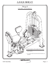
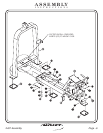
FRAME ASSEMBLY
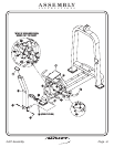
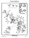
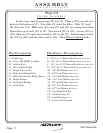
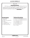
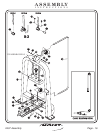
Step 2d
In this step, start by pressing (29) into (2). Place a (28) over the two
holes in the bottom of (2). Now slide (31) into the holes. Slide (27) and
the (26) onto (31). Make sure (26) and (27) and (31) are sitting level, then
fasten the top of each (31) to (2). Next attach (23) to (22). Secure (22) to
(26), slide on (24) and attach another (23) to the (2). Attach bigger end of
the (CL) to (22), and the other end to (25). Then bolts.Wrench tighten
FITNESS SYSTEMS
R
HOIST
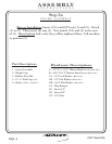
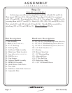
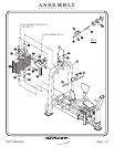
2 - Weight Cage
22 - Center RH (BRK) Assembly
23 - Add On Rods
24 - 5lbs. Add On Weight
25 - Weight Selector Pin
26 - 20lbs. Steel Weight Plate
27 - 20lbs. Intermediate Weight Plates
28 - Weight Bumper
29 - Guide Rod Bushing
31 - Guide Rods
Part Descriptions
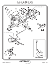
F - 3/8”-16 x 1” Button Head Screw
H - 3/8”-16 x 1” Button Head Screw
J - 3/8”-16 x 2 3/4” Button Head Screw
K - 5/16”-18 x 1” Button Head Screw
AE - 3/8” Flat Washer
AF - 3/8” Lock Washer
AG - 5/16” Flat Washer
AH - 5/16” Lock Washer
CD - Top Weight Roll Pin
CE - Guide Bearing
CF - Guide Bearing
CL - Selector Pin Lanyard
(White Zinc)
(Black Zinc)
(White Zinc)
(Black Zinc)
(White Zinc)
(White Zinc)
(Black Zinc)
(Black Zinc)
(Tall)
(Short)
AJ - 3/8” Split Washer
AK - 3/8” Lock Washer
AL - 3/8” Flat Washer
(White Zinc)
(Black Zinc)
(Black Zinc)
Hardware Descriptions
2407 Assembly
Page 11