


ASSEMBLY
INSTRUCTIONS
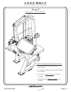
FRAME ASSEMBLY
Step 2d
14 - Seat Adjuster
15 - Belt Assembly
17 - Latch Assembly
20 - Cam Belt
Part Descriptions
M - 3/8” x 3/4” Button Head Cap Screw
P - 3/8” Internal Lock Washer
R - C-Clip
AD - 3 1/4” Pulley
AE - EZ Glide Sleeve
AF - Adjustment Spring
AG - 1.55 x .25 Dia. Shaft
AP - 3/8” x 3/4” Square Head Set Screw
BB - 1/4” Locking Nut
BG - 3/8” Flat Washer (white zinc)
BL - Serrated Hex Nut
Hardware Descriptions
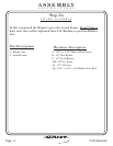
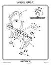
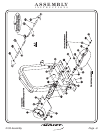
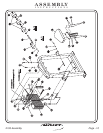
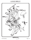
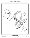
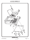
In this step start by
slide the Cam Belt
through the Roller Bracket on the top of the Weight Cage. Then, secure
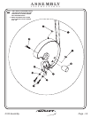
the two 3 1/4” Pulleys to the Weight Cage under the Cam Belt. Next,
attach the Latch Assembly to the Seated Assembly by sliding the 1.55 x
.25 Dia. Shaft through the mounts and through the Adjustment Spring
and secure with the C-Clip; also, insure that the Adjustment Spring ends
are pointing down to ensure that the Latch Assembly locks the Seat
Adjuster in place. Next slide the two EZ Glide Sleeves into the Seated
Assembly from the top down until the locating boss snaps into the
location hole. Next slide the Seat Adjuster in the Seated Assembly.
bolts.
Wrench
tighten
attaching the Belt Assembly to the Weight
Assembly(prior to attaching the Cam Belt). Next,
FITNESS SYSTEMS
R
HOIST
Page - 11 2103 Assembly