


7
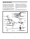
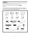
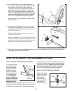
4. The Console (9) requires two ÒAAÓ batteries (not
included); alkaline batteries are recommended.
Refer to drawing A. Remove the four indicated
screws and lift off the front of the Console. Press two
batteries into the battery holder as shown in drawing
B. Make sure that the negative (Ð) ends of the bat-
teries are touching the springs. Reattach the front of
the Console. Make sure that the three wires are
extending from the back of the Console.
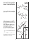
While another person holds the Console (9) near
the Upright (6), plug the Extension Wire (18) into the
back of the Console. Next, attach the ground wire
and the Console (9) to the Upright (6) in the follow-
ing way:
¥ Peel the backing off one side of the Double-sided
Tape (81). Stick the Tape firmly to the underside of
the Upright (6) so it covers the indicated hole.
¥ Peel the backing off the other side of the Tape (81).
Slide a Star Washer (80) onto a M4 x 25mm Screw
(21) and push the Screw up through the Tape and
the indicated hole. Next, slide another Star Washer
(80) and the ground wire onto the Screw.
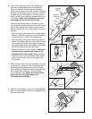
¥ Set the Console (9) on the Upright (6). Make sure
that there is one console wire in each of the
indicated slots in the Upright. Tighten the M4 x
25mm Screw (21) into the Console. Next, tighten
three Console Screws (20) into the Upright and
the Console.
6. Attach the Cup Holders (14) by firmly pushing them
down into the indicated holes in the Upright (6) until
they are seated fully.
14
14
6
4
6
9
Slots
80
81
80
Hole
Console
Wires
Ground
Wire
6
21
20
18
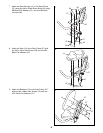
5. While another person holds the Handlebar (16) near
the Upright (6), connect the two Pulse Wires (22) to
the corresponding console wires on the Console.
Next, attach the Handlebar to the Upright with three
M8 x 45mm Button Screws (17) and three M8
Curved Washers (28). Make sure that the Pulse
Wires (22) are not caught between the
Handlebar and the Upright.
17
28
22
16
6
5
Screws
Batteries
Battery
Holder
B
A
Console
Wires
9
A
9