


6
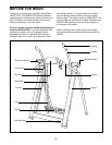
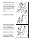
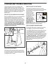
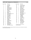
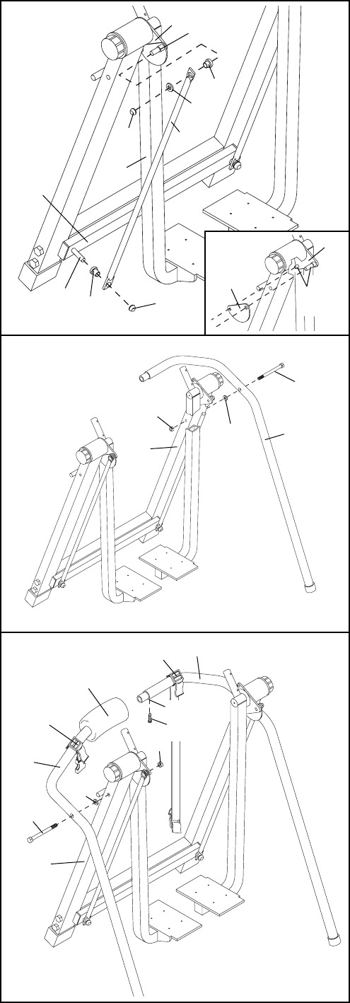
3. Attach the Right Frame Section (6) to the Right
Upright (2) with a 3/8Ó x 5 1/2Ó Screw (42), a
Plastic Spacer (41), and a 3/8Ó Nylon Locknut
(43). Do not tighten the Nylon Locknut yet.
4. Slide the long end of the Nylon Strap (59) onto
the Right Frame Section (6) as shown. Slide the
short end of the Nylon Strap (59) and the Hip Pad
(28) onto the Left Frame Section (5).
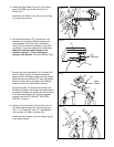
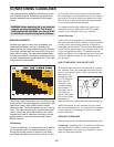
Slide the Left and Right Frame Sections (5, 6)
together. Make sure that the indicated hole is
accessibleÑif necessary, slide the Hip Pad (28) to
the side. Attach the Frame Sections with a #8 x
3/4Ó Screw (23). Do not tighten the Screw yet.
Attach the Left Frame Section (5) to the Left
Upright (1) with a 3/8Ó x 5 1/2Ó Screw (42), a
Plastic Spacer (41), and a 3/8Ó Nylon Locknut
(43).
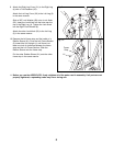
Tighten all parts used in steps 1, 3, and 4. If
the parts are not properly tightened, a
squeaking noise may occur during use.
Center the Hip Pad (28) on the Left and Right
Frame Sections (5, 6).
Fig. 3
6
2
42
41
43
7
9
3
40
16
60
40
Pin
Pin
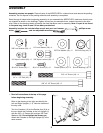
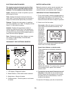
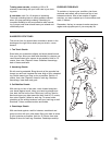
2. Refer to figure 2b. Slide a Finger Guard (54) onto
the pins on the Left Pivot Bracket (7). Note: The
Finger Guards may already be attached.
Find the Left Link Arm (11), which is labeled with a
ÒleftÓ sticker. Make sure that there is a Bronze
Bushing (16) in each end of the Link Arm. Slide
one end of the Link Arm onto the indicated pin on
the Left Pivot Bracket (7). Slide a 3/8Ó Flat Washer
(60) onto the same pin and tap a 3/8Ó Axle Cap
(40) onto the pin. Slide the other end of the Link
Arm onto the pin on the Rocker Arm (9). (Note: It
may be necessary to pivot the Rocker Arm and the
Left Leg [3] slightly.) Tap a 3/8Ó Axle Cap (40) onto
the pin.
Attach the other Finger Guard and the Right Link
Arm (not shown) in the same manner.
Fig. 2a
11
Fig. 2b
54
7
Pins
16
28
59
59
23
5
42
1
41
43
6
Fig. 4
Hole