


11
CABLE ASSEMBLY
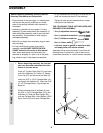
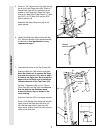
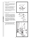
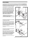
19. Slide a Cable Trap (66) and a 3 1/2” Pulley
(15) onto each 3/8” x 3 3/4” Bolt (68). Insert
the Bolts into the Front Upright (42) from the
direction shown. Hand tighten a 3/8” Nylon
Locknut (21) with a 3/8” Flat Washer (9) onto
each Bolt. Be sure that all parts are orient-
ed as shown. Do not tighten the Nylon
Locknuts yet.
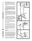
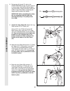
20. Route the Short Cable (23) around the 3 1/2”
Pulley (15) attached to the lower hole in the
Front Upright (42). See the inset drawing.
Be sure that the Cable Trap (66) is turned
to hold the Cable in place and that the
Cable is routed around the Pulley as
shown. Tighten the 3/8” Nylon Locknut (21)
and the 3/8” x 3 3/4” Bolt (68).
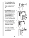
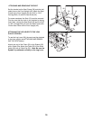
21. Route the Short Cable (23) up around the
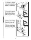
3 1/2” Pulley (15) attached to the upper hole
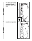
in the Press Frame (17). Be sure that the
Cable Trap (66) is turned to hold the Cable
in place and that the Cable is routed
around the Pulley as shown.
Next, route the Short Cable (23) around the
3 1/2” Pulley (15) attached to the upper hole
in the Front Upright (42). Refer to the inset
drawing. Be sure that the Cable Trap (66)
is turned to hold the Cable in place and
that the Cable is routed around the Pulley
(15) as shown.
21
23
42
15
15
66
21
17
20
23
21
42
15
68
23
Inset shows view
from other side
42
66
15
23
Inset shows view
from other side
42
66
15
19
21
15
15
68
9
42
66