


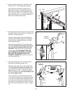
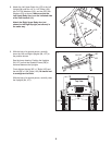
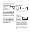

7. Insert the Upright Wire (77) and the Console
Wire (66) into the Right Upright (107).
Set the console assembly on the Uprights (84,
107). Be careful not to pinch the wires. While
a second person holds the console assembly,
attach it with four 5/16" x 1" Bolts (64) and four
5/16" Star Washers (8); start all four Bolts and
then firmly tighten them.
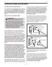
Plug in the power cord as described on page
11, and turn on the power as described on page
13. (Note: The treadmill may automatically rise
to the maximum incline level and then return to
the minimum level.) Adjust the incline to the low-
est incline level as described in step 4 on page
14.
7
Console
Assembly
64
77, 66
64
8
8
107
84
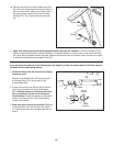
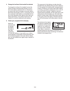
6. With the help of a second person, carefully raise
the Right Upright (107) and the Left Upright (not
shown) to a vertical position.
Have the second person hold the console as-
sembly near the Right Upright (107) as shown.
Look under the console assembly and locate
the Console Wire (66).
Connect the Upright Wire (77) to the Console
Wire (66). See the inset drawing. The connec-
tors should slide together easily and snap
into place. If they do not, turn one connector
and try again. IF THE CONNECTORS ARE
NOT CONNECTED PROPERLY, THE CON-
SOLE MAY BE DAMAGED WHEN THE
POWER IS TURNED ON. Remove the wire tie
from the Upright Wire.
6
107
Wire
Tie
77
66
Console
Assembly
77
66
8
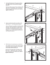
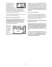
5. Attach two Base Pads (82) to the Base (108)
with two #8 x 1" Tek Screws (83) as shown.
I
nsert the other Extension Leg (89) into the
Base (108) as shown. Hold two Extension Leg
N
uts (67) in the bottom of the Extension Leg.
Next, insert two 5/16" x 2 1/4" Bolts (65) into the
top of the Extension Leg, and firmly tighten the
Bolts into the Extension Leg Nuts.
5
89
8
2
82
108
83
65
67