


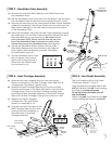
a) Remove the Plastic Stoppers and the two small Phillips
Screws at the back of the Seat Carriage Tube. Slide off the
Carriage End Cap letting it gently hang.
b) Holding the Seat Carriage Assembly by the front of Seat
Cushion and the top of the Back Rest, slide it onto the Seat
Carriage Tube. Lift up on the Seat Carriage Locking Knob
and slide the Seat Carriage Assembly on the Seat Carriage
Tube until the Seat Carriage Locking Knob locks into a slot.
c) Replace the Plastic Stoppers,
Carriage End Cap and Phillips
Screws you removed in (a).
d) Plug the wire from the back of the
Seat Carriage Tube into the wires
coming from the Handlebar on
the lower back of the Seat
Carriage Assembly.
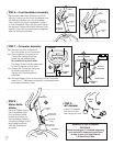
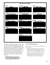
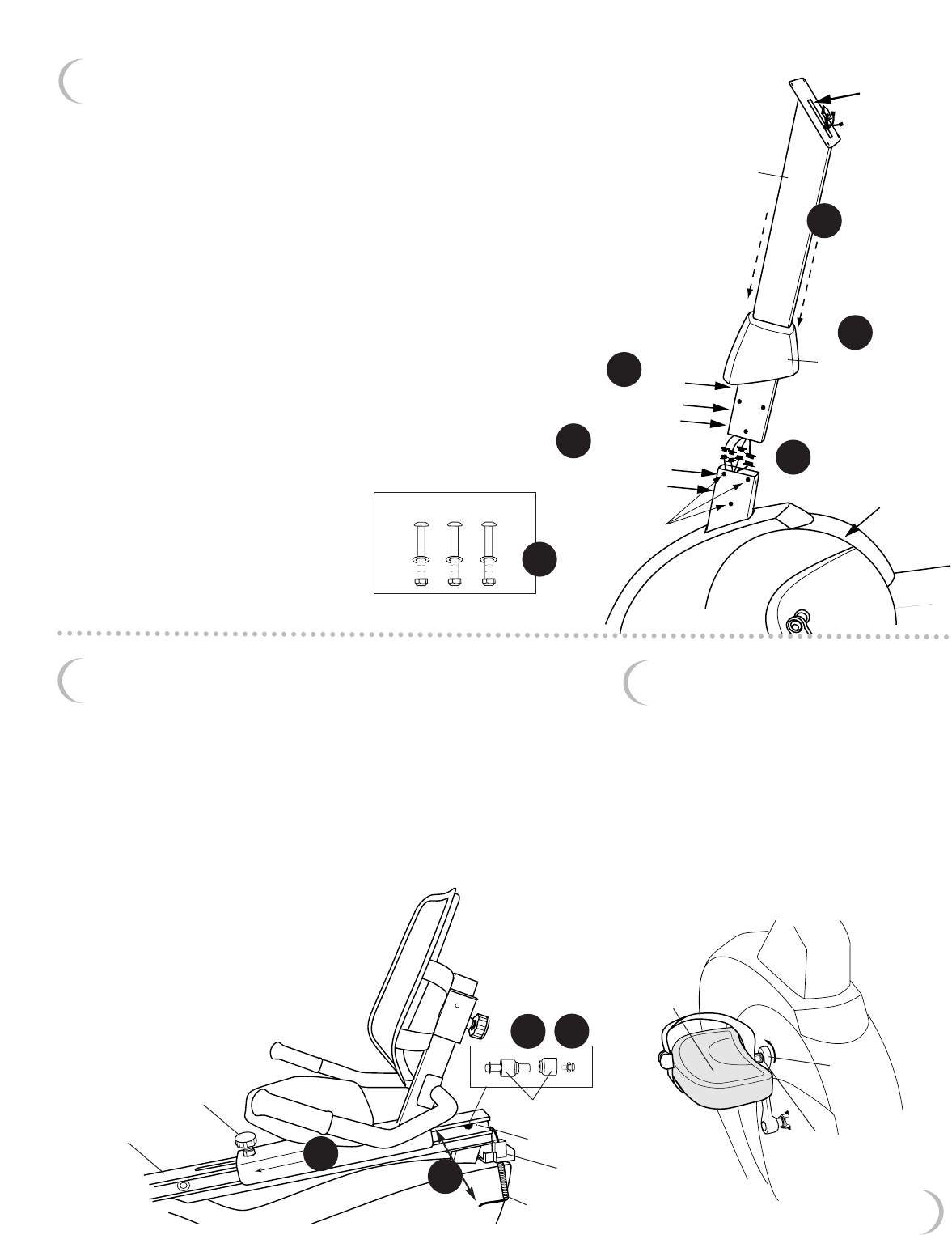
STEP 3 – Handlebar Tube Assembly
a) Remove the two Allen Bolts, Washers and Phillips Screw from
the Handlebar Tube.
b) Slip the Handlebar Tube Cover onto the Handlebar Tube as shown.
The Handlebar Tube should lean back towards the back of unit.
c) Remove the wire tie from the wires inside the Main Frame Assembly
where the Handlebar Tube will go. Attach the four wires from the
Main Frame Assembly to the four wires coming out the bottom
of the Handlebar Tube.
d) Insert the Handlebar Tube into the Main Frame Assembly, tucking
the wires down into the Main Frame Assembly. Reinsert the Allen
Bolts and Washers you removed in (a). Be careful not to
pinch the wires. NOTE: Gently pull the wires up from the
top of the Handlebar Tube to prevent any slack in the
wires at the base of the Handlebar Tube. Hand tighten.
e) Secure the Handlebar Tube in place with the three
Allen Bolts, Washers and Nylon Nuts from the Fastener
Pack.Tighten with the Wrench provided. Also tighten
the bolts used in step (d).
f) Let the Handlebar Tube Cover
slip into place. Push it down
gently until it clicks. Secure in
place with the Phillips Screw
you removed in (a).
handlebar
tube
allen bolts,
washers & nuts
from fastener
pack
opening in
handlebar tube
towards back
main
frame
assembly
back of unit
re-insert allen
bolts & washers
from step a
remove allen
bolts & washers
phillips
screw
handlebar
tube
cover
M8 x 60mm allen bolts,
M8 washers and M8 nylon nuts
7
3d
3a
3c
3d
3e
3b
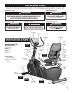
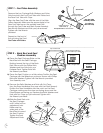
STEP 5 – Foot Pedal Assembly
The Foot Pedals and the Foot Pedal
Cranks are marked “L” and “R”.
Using the Wrench provided, attach the
left Foot Pedal to the left Crank rotating
the Wrench counter-clockwise.
Do not try to turn clockwise. You will
strip the threads.
Attach the right Foot Pedal to the right
Crank rotating the Wrench clockwise.
left side shown
looking from the
back of the unit
left
crank
“L” & “R”
markings are
located on the
ends of the
pedal shaft.
left foot
pedal
STEP 4 – Seat Carriage Assembly
4a
4b
4c
phillips
screw
plastic stoppers
wire
4d
seat carriage
tube
seat carriage
locking knob
carriage
end cap