


9
5 6
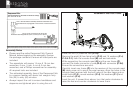
FINAL SETUP &
INSTALLATION
Move the unit into
final position with
the help of the front
transport rollers.
This unit is heavy.
Safe transport may
require more than
one person. Carefully
lift and support the
rear end of the unit
until both wheels
touch the ground.
Slowly roll into
position.
After moving the
unit, ensure all four
feet are touching
the floor. Review
assembly step #1
above for leveling
instructions.
Inspect the unit
for loose bolts,
hardware, knobs or
pins.
Plug the AC adaptor
in a 120 Volt power
supply. Plug the
opposite end into
the input jack found
at the rear of the unit
(CC).
A-1
B-11 B-3 B-1
B-13
N
A-6A-2 A-5
A-2
C-28
A
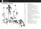
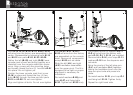
The console hinge cover (A-1) is installed
onto the console at the factory. Remove the
four (4) screws (A-2) from the back of the
console hinge cover (A-1) and set the parts
aside. Four (4) more A-2 Phillips screws will
now be visible on the backside of the console.
Remove these, and set aside.
While supporting the console (A), feed wire
connectors A-6 & A-5 through inside of the
console hinge cover A-1 and join connector A-6
with connector B-11. Join connectors A-5 and
B-3. Make sure all connections are solid. Slide
the console hinge cover A-1 downward on the
cable to rest on the console mast.
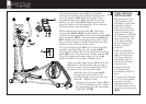
Tilt the console hinge (B-1) to its most upright
position and feed the four (4) screws (A-2)
through the under side of the console mounting
plate (B-1) and into the back of the console (A).
Only the upper and lower holes of the hinge
plate are used in this step. Tighten firmly.
Align console hinge cover (A-1) with the
backside of the console, taking care to
tuck the wires into the backside of the
console or into the console mast.
Feed the four (4) screws (A-2)
through the back side of the
console hinge cover and into the
console. Tighten firmly.
Connect the power supply (N) to
a 120 Volt power source. Insert
the opposite end into the power
input jack (C-28).