


4
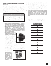
Understanding and testing the locking
mechanism function
The Bowflex
®
SelectTech
®
Dumbbell features a patent
pending locking mechanism designed to assure proper
and complete selection of the weight plates as well as to
ensure weight plate retention during the workout. It is
important that you fully understand the function of this
mechanism and periodically test it to ensure it is properly
functioning.
Function
The locking mechanism provides two key functions:
1. The mechanism will only allow the adjustment
knobs to be rotated when the dumbbell handle is
completely inserted and engaging the dumbbell
base.
2. The mechanism is designed to lock the dumbbell
handle to the base if either adjustment knob is not
fully engaging the selected weight plates.
Purpose
The locking mechanism serves two important purposes:
1. The mechanism will prevent deselecting (drop
-
ping) weight plates from the dumbbell when it is
NOT in the dumbbell base.
2. The mechanism will prevent partial selection of
the weight plates in which the plates are not fully
supported and the locking pin is not fully engaged.
Given the importance of this locking mechanism, it is
critical that you understand how it operates and how to
periodically test it to make sure it is functioning correctly.
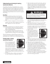
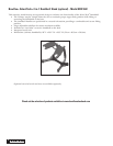
Testing proper locking
mechanism function
1. With the dumbbell handle
set in the dumbbell base,
turn both adjustment knobs
to the number 10. You will
know you have fully and cor-
rectly selected the number
when you feel the adjustment
knob settle into a notch (known as a detent). You
will also hear a slight, but audible, clicking noise
that corresponds with the detent locations for each
number.
2. You should be able to withdraw the handle from
the base leaving all the weight plates behind.
3. With the handle removed from the base, grab one
adjustment knob with your other hand and gently
attempt to turn the knob. The knob should not
rotate. A locking pin in the mechanism will have
engaged the rotational assembly when the unit was
withdrawn from the base. Perform this test with all
adjustment knobs.
4. After confirming the proper function of the lock
-
ing mechanism as described above, return and fully
insert the dumbbell handle back into the base
assembly.
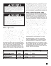
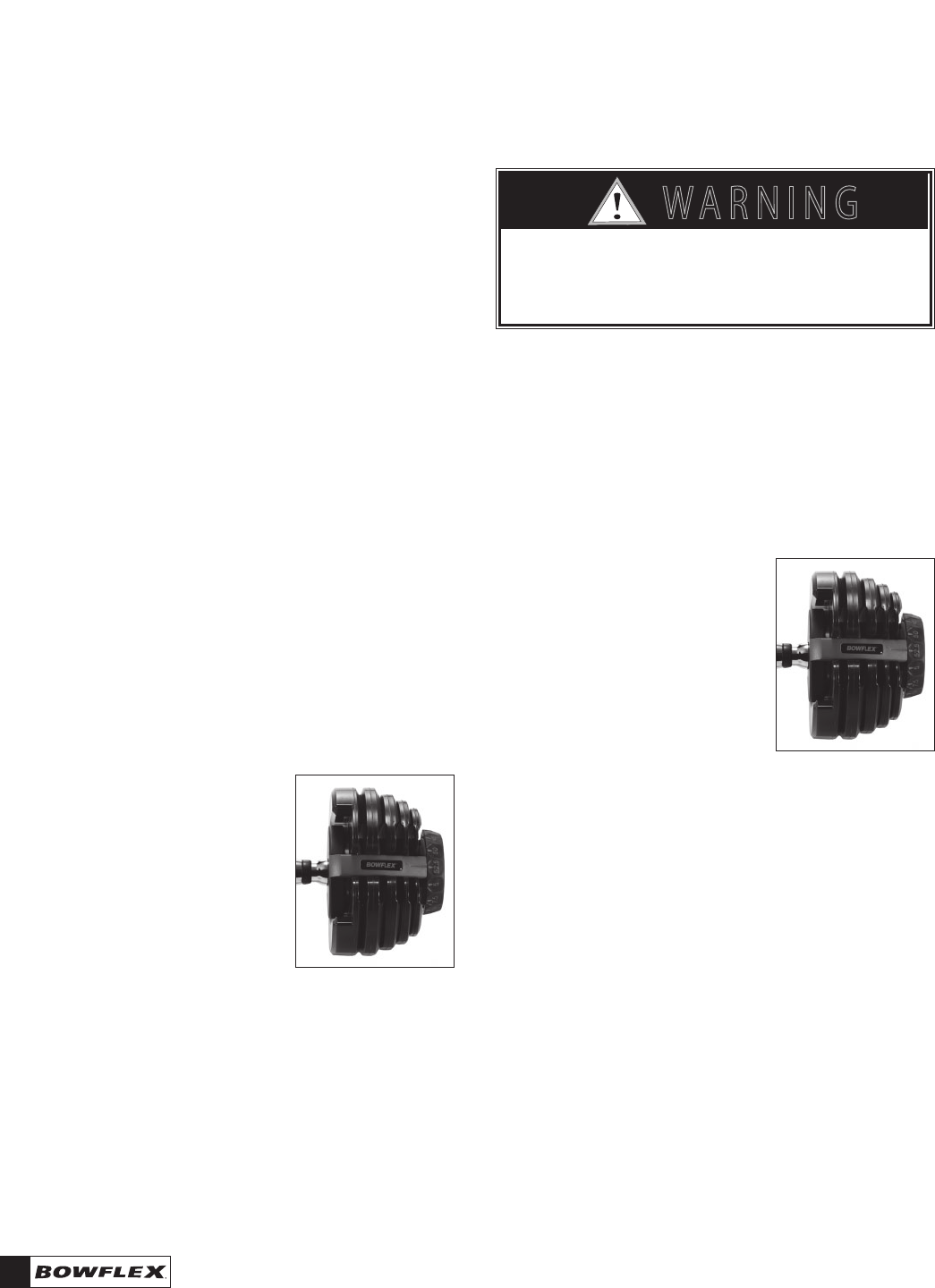
5. With the handle back in the base, turn the adjust
-
ment knob on one side to a position that is in-
between the 10 and 15 number. This represents an
incomplete weight selection where the adjustment
knob has not fully selected a weight and the knob
is in-between the selection
detents (clicks).
6. With the selection knob in
this improper position, gen-
tly attempt to lift up on the
handle to remove it from the
base. You should find that the
handle is locked to the base
and cannot be removed with
light pressure as it can nor-
mally.
7. Return the improperly selected adjustment knob to
a full and proper weight selection and assure that
the dumbbell handle can once again be removed.
8. Repeat this test for all adjustment knobs.
9. Assure the entire dumbbell handle assembly is
properly tightened. Do this by setting the adjust-
ment knobs to 10 pounds and removing the handle
assembly from the base. Grab both adjustment
knobs and very slightly push and pull the knobs
toward and away from the handle grip. The knobs
should not exhibit free play and all of the selection
discs should feel tightly connected.
10. You have now tested the function of the locking
mechanism. We suggest you repeat this test periodi-
cally (once a month) to confirm the proper func-
tion of the locking mechanism.
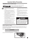
Do not use a great deal of force in an attempt to
turn the locked adjustment knob. Excessive force
may damage the locking mechanism.
7 ! 2 . ) . '
! 4 4 % . 4 ) / .
$ ! . ' % 2
)--%$)!4%!#4)/.2%15)2%$
# ! 5 4 ) / .