


Chapter
3
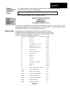
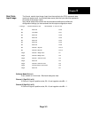
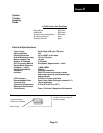
The 8-word module input image (input from the module to the CPU) represents data
words and status words. Input words (data words) hold the input data that represents
the values of the sensor inputs.
Data Table
Input Image
Input words (status bits) contain the various status conditions and reflect the
configuration settings you have entered into the output configuration words.
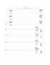
(I =file type : =element delimiter 2 =slot . =word delimiter 0 =word / 2 =bit)
Bit Reserved I:e.0/0
Bit Trim Mode I:e.0/1
Bit Reserved I:e.0/2
Bit Reserved I:e.0/3
Bit Reserved I:e.0/4
Bit Reserved I:e.0/5
Bit Reserved I:e.0/6
Bit Channel 1 Sign Bit I:e.0/14
Bit Channel 2 Sign Bit I:e.0/15
Integer Channel 1 Weigh Value I:e.1
Integer Channel 2 Weigh Value I:e.2
Integer Channel 1 A/D Trim Value I:e.3
Integer Reserved I:e.4
Integer Channel 2 A/D Trim Value I:e.5
Integer Communication Fault Counter I:e.6
Integer Reserved I:e.7
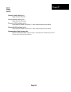
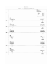
Calibrate Mode Bit (I:e/1)
If set, module is in trim mode. Bit should always be clear.
Channel 1 Sign Bit (I:e/14)
If Channel 1 signal is positive value, Bit = 0 and negative value Bit = 1.
Channel 2 Sign Bit (I:e/15)
If Channel 2 signal is positive value, Bit = 0 and negative value Bit = 1.
Page 3-3