


Chapter
3
Channel
Configuration
Data and
Status
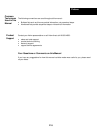
This chapter explains how the Weigh Scale module and the processor communicate
through the module's input and output image.
For CompactLogix / RSLogix™ 5000 setup, please refer to Appendix A
With RS Logix500 software, verify the module ID code.
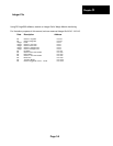
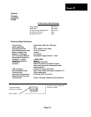
Expansion General Configuration
Weigh
Scale
Module ID
Code = 1
Vendor ID = 3
Product Type = 9
Product Code = 1
Series/Major Rev/Minor Rev = D
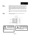
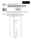
No special I/O configuration (SPIO CONFIG) information is required. The module ID code
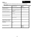
automatically assigns the correct number of input and output words. The following memory map
shows how the output and input image tables are defined.
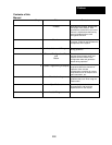
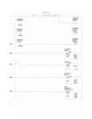
The 8 word output image (output from the CPU to the module) contains
Information that you configure to define the way a specific channel will work.
Output Image
Example – If you want to configure channel 2 on the module located in slot 4
in the SLC chassis, your address would be O:4.2.
(
o = file type : =element delimiter 4=slot .=word delimiter 2=word)
Bit Reserved O:e.0/0
Bit Reserved O:e.0/1
Bit Reserved O:e.0/2
Bit Zero Stabilize 0=Off 1=On O:e.0/3
Bit LSD Flicker 0=Off 1=On O:e.0/4
Bit Vibration Filter 0=Off 1=On O:e.0/5
Bit Channel 2 Trim O:e.0/6
Bit Coarse Zero Up Adjust O:e.0/7
Bit Channel 1 Trim O:e.0/8
Bit Reserved O:e.0/9
Bit Reserved O:e.0/10
Bit Reserved O:e.0/11
Bit Coarse Zero Down Adjust O:e.0/12
Bit Clear Tare O:e.0/13
Bit Tare O:e.0/14
Bit Channel Toggle 0=CH1 1=CH2 O:e.0/15
Integer Channel 1 Scale value O:e.1
Integer Channel 1 mV/V Setting O:e.2
Integer Channel 1 A/D Trim Setting O:e.3
Integer Channel 2 mV/V Setting O:e.4
Integer Channel 2 A/D Trim Setting O:e.5
Integer A/D Samples Setting O:e.6
Integer Channel 2 Scale value O:e.7
Page 3-1