2-10
Making Measurements
Modulating the Output Light
Modulating the Output Light
The rear panel of the instrument is equipped with a
MODULATION INPUT
connec-
tor. You can use this connector to digitally modulate the source for applica-
tions using lock-in techniques. (Refer to “Ambient Light Suppression” on
page 2-7.) Or, you can completely disable its output light.
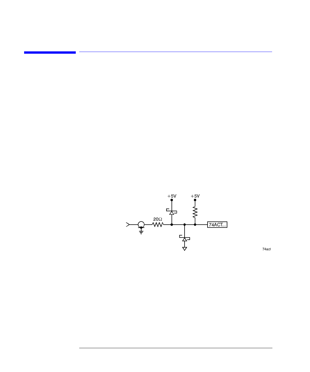
Digital modulation requires a TTL compatible signal. Modulation rates can
range from DC to 300 Hz. A “high” TTL value turns the source on. A “low” TTL
value turns the source off. The TTL low state is defined to be within 0 to
0.8 Vdc. The TTL high state is defined to be within 2.0 to 5 Vdc.
The following schematic shows the input circuitry for the
MODULATION INPUT
connector.
If no signal is present on the
MODULATION INPUT
connector, the source is turned
on. If you want to turn the output off, simply connect a BNC short to the rear-
panel modulation input. You can order a BNC short from Agilent Technologies
using the following part number: 1250-0774.


