9
9.
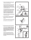
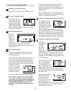
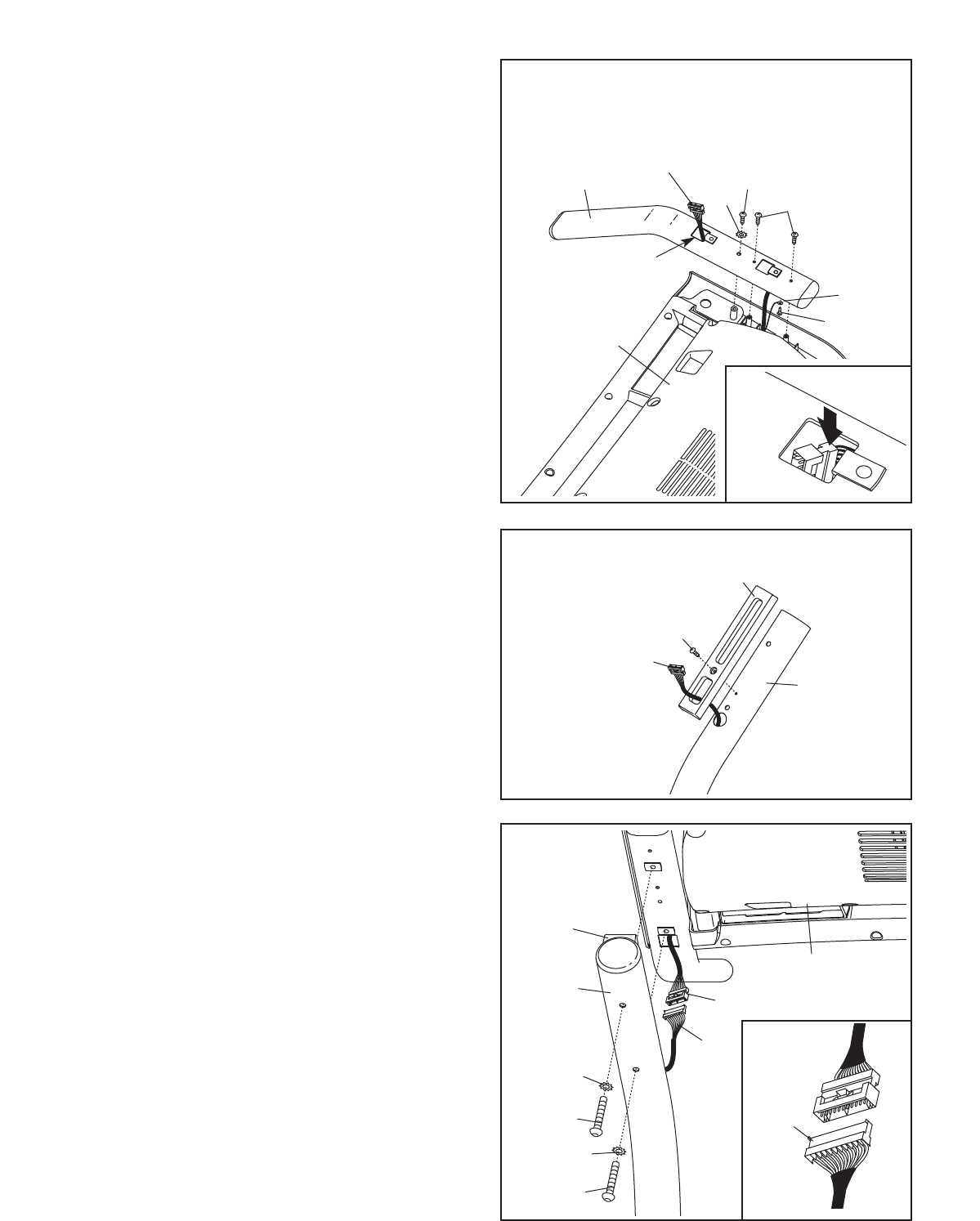
While another person holds the Console Base
(26) near the right Handrail (18). Connect the
console wire to the Upright Wire (28) as shown
in the inset drawing. Important: If the connec
-
tors are oriented correctly, they will slide to-
gether easily and snap into place. If the con-
nectors are not oriented correctly, the con-
sole may be damaged when the power is
turned on. Insert the connectors into the Right
Upright (36).
Attach the Console Base (26) to the Right
Upright (36) and the Left Upright (not shown)
with four Handrail Bolts (20) and four Handrail
Star Washers (19) (only one side is shown).
Start all four Handrail Bolts before tightening
any of them.
20
19
36
26
28
20
19
9
Console Wire
7
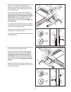
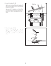
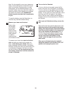
. Set the console assembly face down on a soft
surface to avoid scratching it. Hold a Handrail
(18) near the console assembly.
N
ext, insert the console wire into the hole in the
bottom of the Handrail (18) and out of the indi-
cated square hole. If necessary, grip the con-
nector with needlenose pliers
only in the area
indicated by the arrow (see the inset drawing.)
Then, attach the ground wire to the Handrail with
a Silver Ground Screw (11).
Next, set the Handrail (18) on the console as-
sembly.
Make sure that no wires are pinched.
Finger tighten a Console Bolt (22) with a 1/4"
Star Washer (21) into the Handrail, and then
start two 3/4" Screws (2) into the Handrail.
Tighten the Console Bolt and then the two
Screws; do not overtighten the Screws.
Attach the other Handrail (not shown) to the con-
sole assembly in the same way. Note: There are
no wires on the other side.
7
Ground
Wire
Console
Wire
Console
Assembly
Square
Hole
18
22
21
2
11
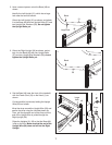
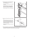
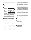
8. Insert the Upright Wire (28) through a Handrail
Spacer (88) as shown. Attach the Handrail
Spacer to the Right Upright (36) with a 3/4"
Screw (2).
Attach the other Handrail Spacer (not shown) to
the Left Upright (not shown) as described above.
Note: There is not a wire on the left side.
8
28
36
2
88
28
18


