


11
Inspect and tighten all parts of the exercise cycle reg-
ularly. The exercise cycle can be cleaned with a soft,
damp cloth. To prevent damage to the console, keep
liquids away from the console and keep the console
out of direct sunlight.
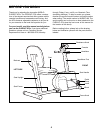
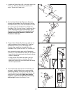
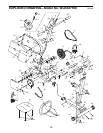
CRANK ADJUSTMENT
If the arms of the
Crank (7) become
loose, they should
be tightened in
order to prevent
excessive wear.
Loosen the Hex
Crank Nuts (14)
on the left arm of
the Crank. Place
the tip of a stan-
dard screwdriver in one of the slots in the slotted
crank nut. Tap the screwdriver with a hammer to turn
the slotted crank nut counterclockwise until the arms
are no longer loose. Do not overtighten the slotted
crank nut. When the slotted crank nut is properly
tightened, tighten the Hex Crank Nuts.
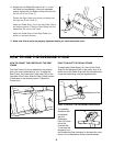
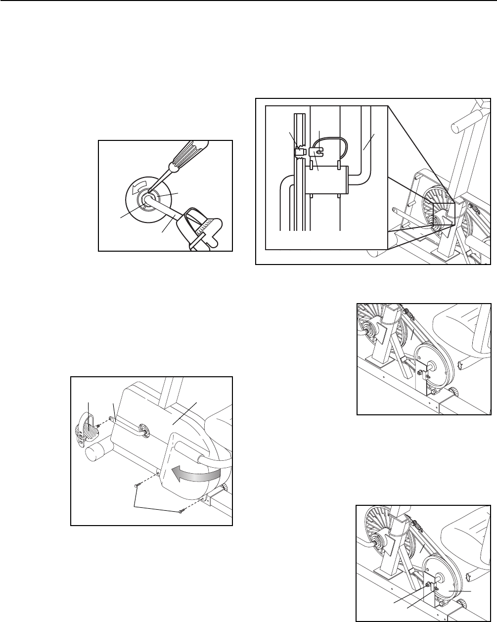
HOW TO ADJUST THE REED SWITCH
If the con-
sole does
not display
correct feed-
back, the
reed switch
may need to
be adjusted.
To adjust the
reed switch,
you must
first remove
the Left Side
Shield (20).
Using an adjustable wrench, turn the Left Pedal (39)
clockwise and remove it. Next, remove the indicated
#8 x 1/4Ó Screws (22). Grasp both Side Shields and
gently pull them apart. Turn the left arm of the Crank
(7) to the position shown, and then carefully slide the
Left Side Shield forward and remove it.
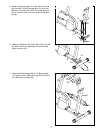
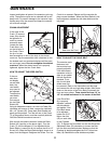
With the left side shield removed, locate the Reed
Switch (42) (see the on the above right). Turn the
Crank (7) until the Magnet (51) is aligned with the
Reed Switch. Loosen but do not remove the #8 x 1/2Ó
Screw (43). Slide the Reed Switch slightly closer to or
away from the Magnet. Retighten the Screw. Turn the
Crank for a moment. Repeat until the console dis-
plays correct feedback. When the Reed Switch is cor-
rectly adjusted, reattach the left side shield and the
left pedal.
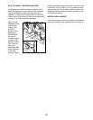
HOW TO ADJUST THE DRIVE BELT
The exercise cycle
features a belt
that must be kept
properly adjusted.
If the belt causes
excessive noise or
slips as you pedal,
the belt should be
checked. To do
this, the left side
shield must first
be removed. Refer to the instructions on this page
and remove the left and right side shields. Next press
down on the center of the Drive Belt (6) between the
front and rear pulleys. There should be from 1/4Ó to
1/2Ó of vertical movement in the center of the Belt.
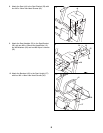
If the Drive Belt
(6) is properly
adjusted, reattach
the side shields
and pedals. If the
Drive Belt needs
to be adjusted,
loosen the 5/16Ó
Nylon Jam Nut
(18) on each side
of the Flywheel
(15). To tighten the Drive Belt, turn the two Drive Belt
Adjustment Nuts (50) clockwise; to loosen the Belt,
turn the Nuts counterclockwise. Make sure that the
Flywheel is straight and tighten the 5/16Ó Nylon Jam
Nuts (18). Reattach the side shields and pedals.
14
Slotted
Crank Nut
7
6
6
18
50
15
42
51
43
7
22
20
39
7
View from the Front
MAINTENANCE