


95
88
91
93
94
41
90
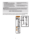
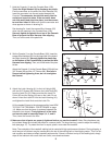
9.
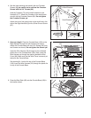
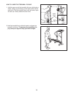
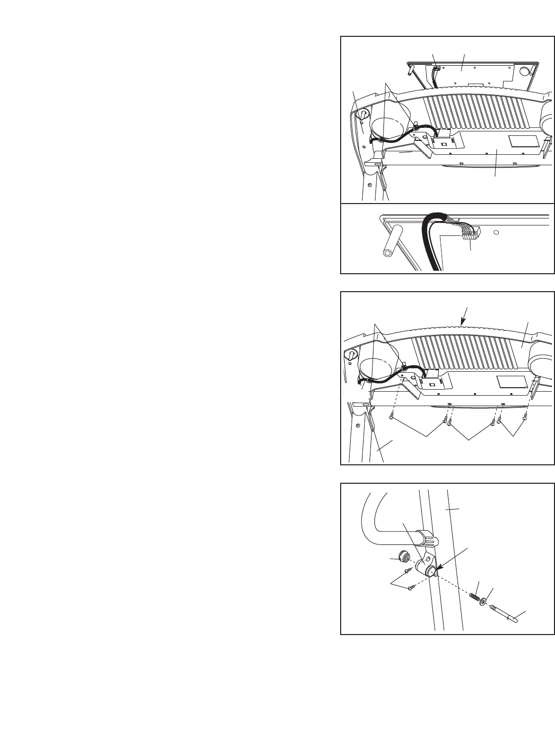
Attach the Latch Housing (41) to the Left Upright (88)
with two 3/4” Screws (90). Remove the Latch Knob (95)
from the Latch Pin (91). Make sure that the Latch Pin
Collar (93) and the Spring (94) are on the Latch Pin as
shown. Insert the Latch Pin into the Latch Housing (41),
and tighten the Latch Knob onto the Latch Pin.
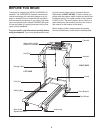
Lift the treadmill frame to the storage position (see HOW
TO FOLD THE TREADMILL FOR STORAGE on page
14). Make sure that the frame is centered between the
Handrails (not shown).
Firmly tighten all of the bolts
and screws used in assembly steps 3, 4, 5, and 8.
Then, lower the frame to the floor.
10.Make sure that all parts are properly tightened before you use the treadmill. Note: Extra hardware may
be included. Keep the included hex keyes in a secure place. The large hex key is used to adjust the walking
belt (see page 17). To protect the floor or carpet, place a mat under the treadmill.
Note: The underside of the treadmill walking belt is coated with high-performance lubricant. During shipping, a
small amount of lubricant may be transferred to the top of the walking belt or the shipping carton. This is a nor-
mal condition and does not affect treadmill performance. If there is lubricant on top of the walking belt, simply
wipe off the lubricant with a soft cloth and a mild, non-abrasive cleaner.
8
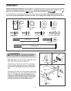
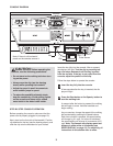
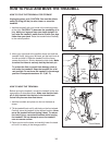
8. Set the Console (1) on the Console Base (100). Insert the
excess Wire Harness (22) into the large hole in the side of
the Right Handrail (6). Securely tighten the plastic ties
on the bottom of the Console Base to prevent the Wire
Harness from slipping. Then, cut off the ends of the plas-
tic ties.
Attach the Console (1) to the Console Base (100) with four
3/4” Screws (90) and two 1/2” Screws (84). Start all six
Screws before tightening them; do not overtighten
the Screws.
9
90
6
90
84
100
1
Ties
Large
Hole
7
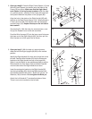
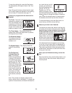
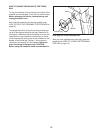
7. Hold the Console (1) near the Console Base (100).
Touch the Right Handrail (6) to discharge any static.
Find the connector on the end of the Wire Harness (22).
Insert the connector into the red socket beneath the
Console. The connector should slide easily into the
socket and snap into place. If the connector does
not slide easily and snap into place, turn the connec-
tor and then insert it. Make sure that the connector and
wires appear as shown in drawing 7a.
See drawing 5a. Insert the excess Wire Harness (22)
down into the opening in the Console Base (100).
Securely tighten the plastic tie on top of the Console
Base to prevent the Wire Harness from slipping.
Then, cut off the end of the plastic tie.
7a
1
22
Ties
22
6
100
9
22