


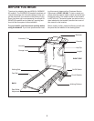
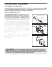
9. Make sure that all parts are properly tightened before you use the treadmill. Note: Extra hardware may
be included. Keep the included hex keys in a secure place; the large hex key is used to adjust the walking belt
(see page 17). To protect the floor or carpet, place a mat under the treadmill.
5
67
84
65
40
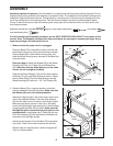
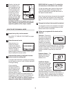
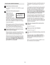
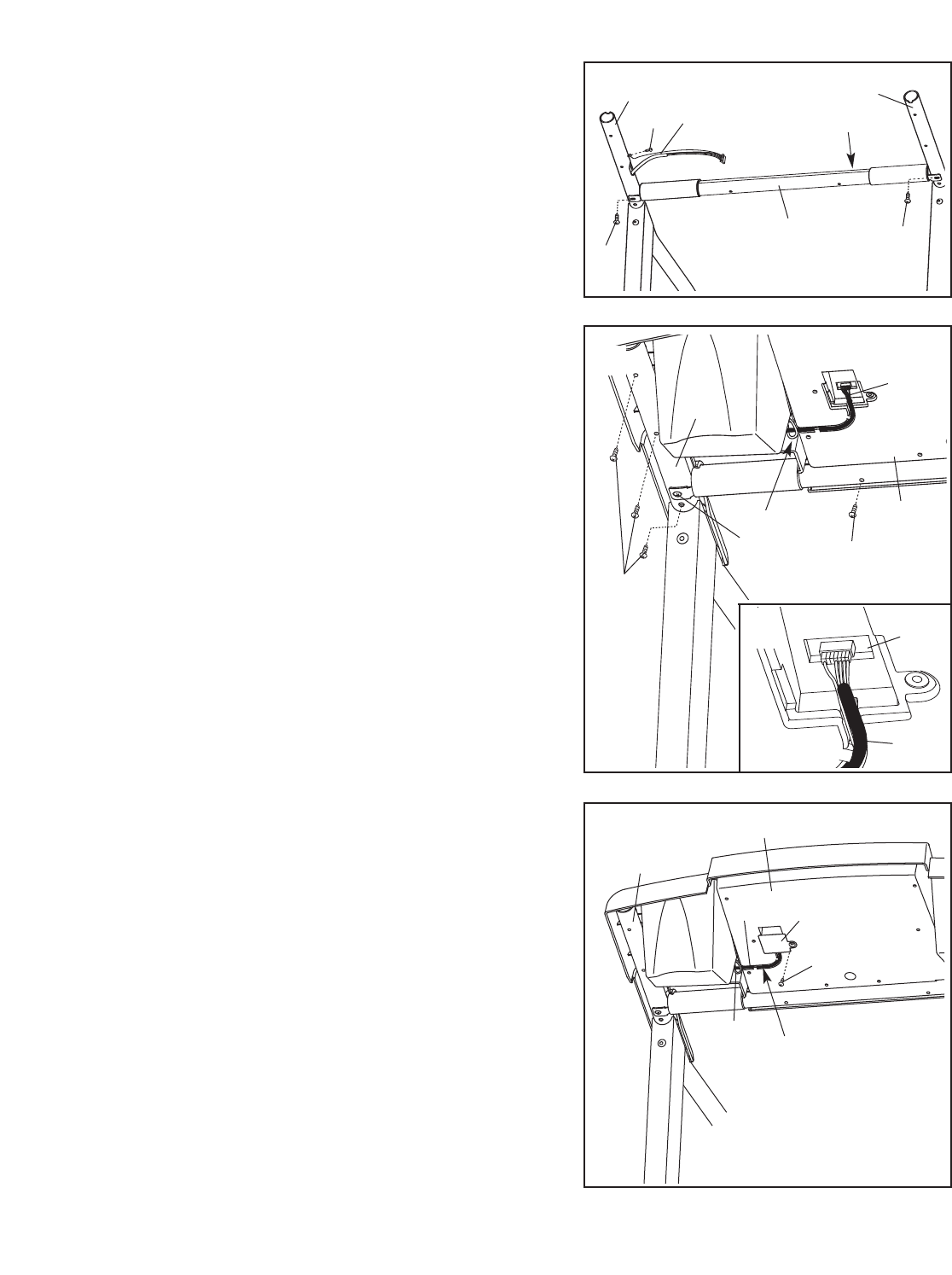
8. Press the Wire Harness (65) into the indicated track in
the Console Base (67). (Note: If there is a cylinder on the
Wire Harness that will not fit into the track, press as
much of the Wire Harness as possible into the track.)
Next, insert the excess Wire Harness into the large hole
in the side of the right Handrail (40). Securely tighten
the nylon tie to prevent the Wire Harness from slip-
ping, and then cut off the end of the nylon tie.
Attach the Access Door (84) to the Console Base (67) with
the 1/2” Screw (5).
See step 5. Tighten, but do not overtighten, the 1”
Bolts (43) and the 4” Bolts (117).
See step 2. With the help of a second person, lower
the Uprights (47, 104). Make sure that the Frame (96)
is centred between the Uprights. Then, firmly tighten
the 3” Bolts (58).
8
Tie
Tie
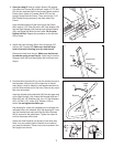
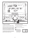
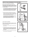
7. Place the Console Base (67) on the right Handrail (40)
and the Left Handrail (not shown).
Insert the Wire Harness (65) through the indicated nylon tie
on the Console Base (67). Next, touch the right Handrail
(40) to discharge any static. See drawing 7a. Insert the
connector on the end of the Wire Harness into the red
socket beneath the Console (69).
The connector should
slide easily into the socket and snap into place.
If the
connector does not slide easily and snap into place, turn
the connector and then insert it. IF THE CONNECTOR IS
NOT INSERTED PROPERLY, THE CONSOLE MAY BE
DAMAGED WHEN THE POWER IS TURNED ON.
Identify the 3/4” Screws (38); be careful not to confuse
the 3/4” Screws with the 1/2” Screw (5). Attach the
Console Base (67) to the right Handrail (40) and the Left
Handrail (not shown) with eight 3/4” Screws (only four
Screws are shown). Start all eight Screws before tight-
ening them. Do not overtighten the Screws.
Tighten the Crossbar Screws (37).
65
67
7
40
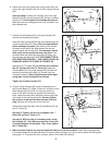
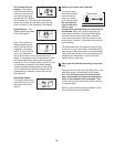
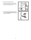
6. Attach the end of the ground wire to the small hole in the
side of the right Handrail (40) with a Silver Ground Screw
(
66).
O
pen part bag C.
A
ttach the Crossbar (39) to the right
Handrail (40) and the left Handrail (40) with two Crossbar
Screws (37).
Do not tighten the Crossbar Screws yet.
Make sure that the rectangular hole in the Crossbar is on
the indicated side.
6
8
65
69
Ground Wire
H
ole
66
39
40
37
37
38
38
37
Track
4
0
7a