8
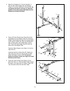
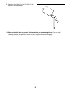
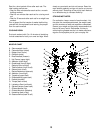
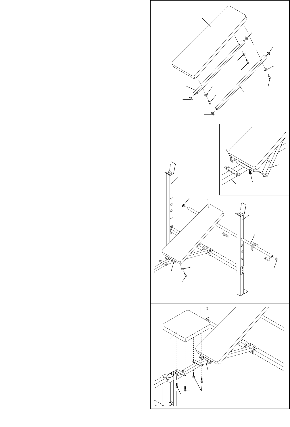
6. Press four 25.4mm Square Inner Caps (15) into
the indicated ends of each Backrest Tube (8).
Attach the Backrest Tubes (8) to the Backrest (9)
with three M6 x 38mm Screws (24) and three M6
Washers (25). Do not tighten the Screws yet.
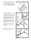
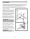
7. Press a 25.4mm Round Inner Cap (19) into each
end of the Support Rod (13).
Insert the end of the Support Rod (13) without the
locking clip through the Uprights (1). Rotate the
locking clip into place around the Upright.
See the inset drawing. With the help of a sec-
ond person, slide the indicated ends of the
Backrest Tubes (8) onto the welded axle on the
Frame (4).
Attach the left Backrest Tube (8) to the Backrest
(9) with a fourth M6 x 38mm Screw (24) and M6
Washer (25). Tighten all four Screws in the
Backrest.
Rest the Backrest (9) on the Support Rod (13).
Tighten the M8 Nylon Locknuts (23) used in
steps 1–3.
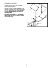
8. Attach the Seat (10) to the brackets on the Frame
(4) with four M6 x 16mm Screws (21).
10
21
21
4
19
24
25
13
8
9
8
8
25
25
25
15
15
15
15
24
24
24
6
1
1
4
Welded Axle
9
8
8
8
19
7


