20
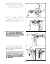
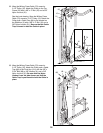
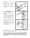
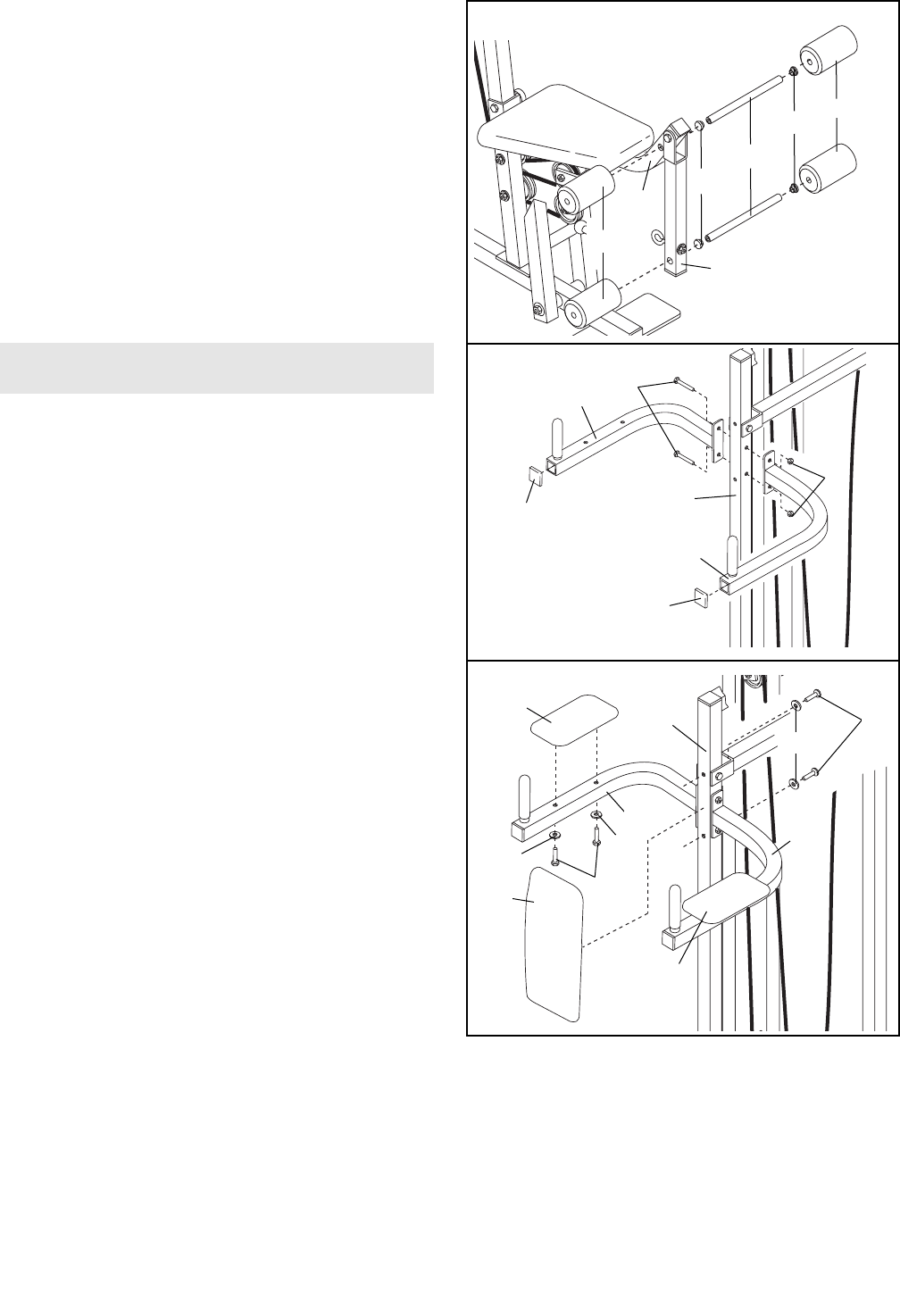
43. Press two 3/4” Round Inner Caps (34) into each
Pad Tube (28).
Insert a Pad Tube (28) into the Front Seat Frame
(36). Slide a Foam Pad (30) onto each end of the
Pad Tube.
Insert the other Pad Tube (28) into the Leg Lever
(29). Slide a Foam Foam Pad (30) onto each end
of the Pad Tube.
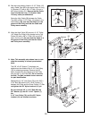
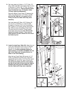
44. Locate and open the parts bag labeled “VKR
ASSEMBLY.”
Press two 1 1/2” Square Inner Caps (32) into the
ends of the Left and Right VKR Arms (79, 80).
Attach the Left and Right VKR Arms (79, 80) to
the VKR Upright (74) with two 5/16” x 3” Bolts
(75) and two 5/16” Nylon Locknuts (3).
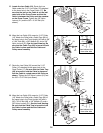
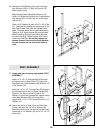
45. Attach the VKR Backrest (77) to the VKR Upright
(74) with two 1/4” x 2 1/2” Screws (43) and two
1/4” Washers (10).
Attach a VKR Armrest (78) to the Right VKR Arm
(80) with two 1/4” x 2” Machine Screws (81) and
two 1/4” Washers (10).
Attach a VKR Armrest (78) to the Left VKR Arm
(79) in the same manner.
43
44
79
80
75
74
3
32
32
81
45
VKR ASSEMBLY
79
30
30
34
34
28
36
29
78
74
78
43
10
10
10
80
77
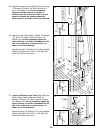
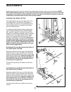
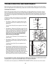
46. Make sure that all parts have been properly tightened. The use of the remaining parts will be explained in
ADJUSTMENTS, beginning on page 21 of this manual.
Before using the weight system, pull each cable a few times to be sure that the cables move smoothly over
the pulleys. If one of the cables does not move smoothly, find and correct the problem. IMPORTANT: If the
cables are not properly installed, they may be damaged when heavy weight is used. See the CABLE
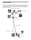
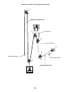
DIAGRAMS on pages 25 and 26 of this manual for proper cable routing. If there is any slack in the
cables, you will need to remove it by tightening the cables. See TROUBLE-SHOOTING AND MAINTE-
NANCE on page 24.


