13
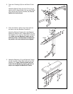
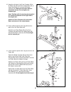
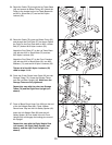
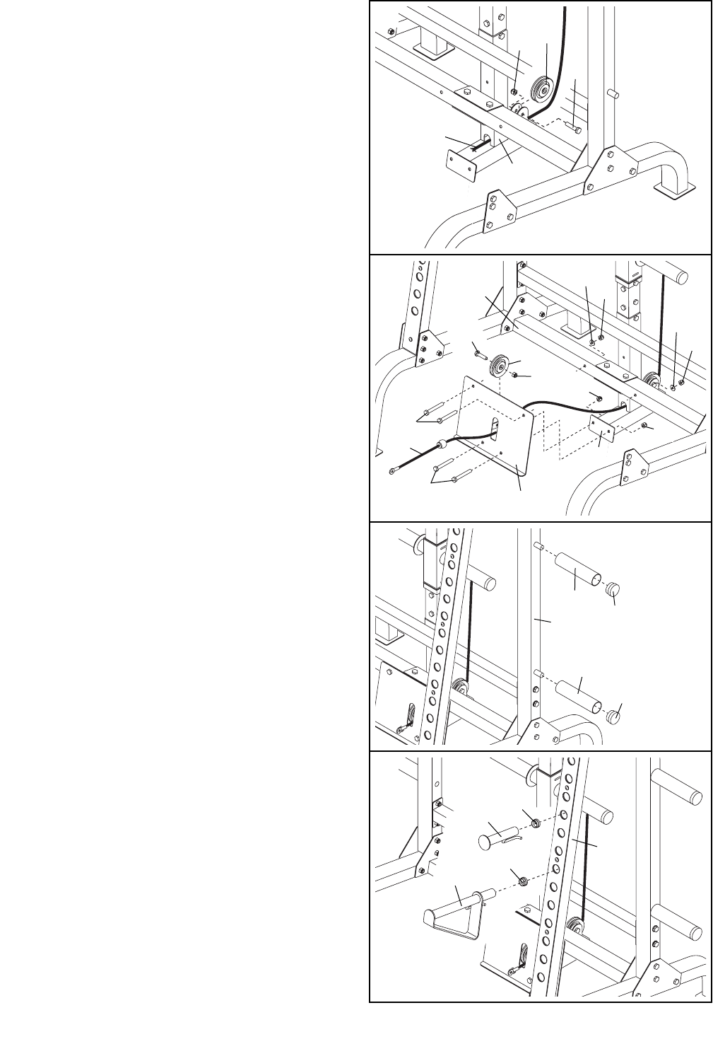
24. Route the Cable (79) through the Lat Tower Base
(49) and around an 89mm Pulley (65). Attach the
Pulley to the bracket on the Lat Tower Base with
an M10 x 45mm Bolt (27) and an M10 Nylon
Locknut (32).
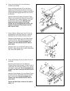
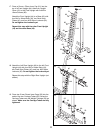
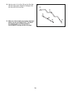
26. Press two 51mm Round Inner Caps (23) into two
Storage Tubes (70). Screw the Storage Tubes
onto the Left Rear Upright (46). Make sure the
Storage Tubes are fully tightened.
Repeat this step with the other two Storage
Tubes (70) and the Right Rear Upright (not
shown).
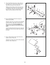
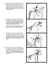
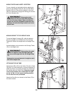
27. Press a 38mm Round Inner Cap (68) into the end
of the Left Weight Rest (80). Press a 38mm
Round Inner Cap into the Left Safety Spotter (81).
Insert the Left Weight Rest (80) and the Left
Safety Spotter (81) into holes in the left Front
Upright (44) and engage the locking pins around
the Upright.
Repeat this step with the Right Weight Rest
(not shown), the Right Safety Spotter (not
shown), and the right Front Upright (not
shown).
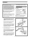
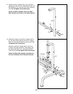
25. Route the Cable (79) under an 89mm Pulley (65)
and through the Foot Plate (57) as shown. Attach
the Pulley to the Foot Plate with an M10 x 45mm
Bolt (27) and an M10 Nylon Locknut (32).
Attach the Foot Plate (57) to the Lat Tower Base
(49) with two M10 x 19mm Bolts (72) and two
M10 Nylon Locknuts (32).
Attach the Foot Plate (57) to the Front Crossbar
(43) with two M10 x 94mm Bolts (18), two M10
Washers (74), and two M10 Nylon Locknuts (32).
Tighten all of the M10 Nylon Locknuts (32)
used in steps 12–18.
24
25
26
27
32
79
49
32
74
32
32
32
32
49
18
57
79
72
23
23
70
70
68
80
81
46
65
43
74
65
27
68
44
27


