14
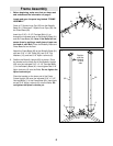
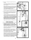
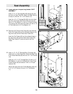
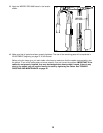
26. Wrap the Long Cable (73) around a 3 1/2” Pulley (5)
in the direction shown. Attach the Pulley and a Cable
Trap (39) to the indicated bracket on the Press Base
(60) with a 3/8” x 2” Bolt (35) and a 3/8” Nylon
Locknut (4). Make sure the Cable Trap is oriented
as shown.
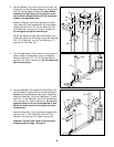
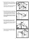
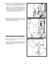
27. Attach a 3 1/2” Pulley (5) and a Cable Trap (39) to
the Press Frame Upright (59) with a 3/8” x 4 3/4” Bolt
(23).
Wrap the Long Cable (73) around the 3 1/2” Pulley
(5) in the direction shown. Hand tighten a 3/8” Nylon
Locknut (4) two turns onto the 3/8” x 4 3/4” Bolt. In
step 31, another Pulley will be attached to the Bolt.
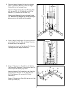
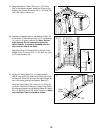
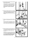
25. Note: For clarity, this and the following drawings
show some parts removed.
Remove the lower 3 1/2” Pulley (5) from the Double
“U” Bracket (36). Then, wrap the Long Cable (73)
over the Pulley (5) in the direction shown. Attach the
Pulley to the Double “U” Bracket (36) with a 3/8” x 1
3/4” Bolt (22) and a 3/8” Nylon Locknut (4). Make
sure the Double “U” Bracket is oriented as
shown.
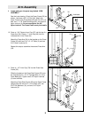
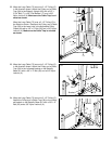
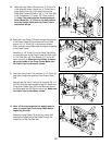
28. Route the Long Cable (73) through the opening in the
Press Frame (53) and wrap the Long Cable around a
3 1/2” Pulley (5) in the direction shown. Then, route
the Long Cable back through the opening in the
Press Frame.
Attach the 3 1/2” Pulley (5) and a Cable Trap (39) to
the indicated hole in the Press Frame (53) with a 3/8”
x 3 1/4” Bolt (28), a 3/8” Flat Washer (17), and a 3/8”
Nylon Locknut (4). Make sure the Pulley is mount-
ed on the inside of the Press Frame (53). Make
sure the Cable Trap is oriented as shown.
26
25
36
4
5
73
60
39
4
73
5
35
22
4
23
73
5
39
59
4
5
39
73
53
28
17
28
27


