


10
19
24
94
28
80
44
76
76
71
74
74
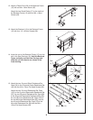
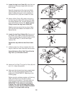
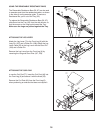
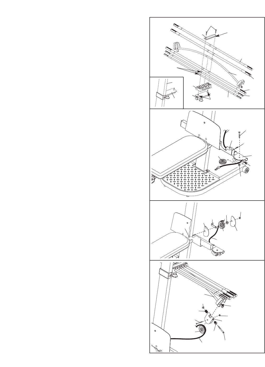
18. Wrap the Long Cable (80) around a 90mm Pulley
(28). Attach the Pulley, a Cable Trap (29), an M10
W
asher (75), and two Finger Guards (110) to the
indicated M10 x 147mm Carriage Bolt (73) with
an M10 Nylon Locknut (76). Make sure the
Cable Trap and Finger Guards are oriented as
shown.
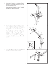
19.
Attach a Pulley Housing (94) to the indicated “U”-
channel on the 10-pound Center Resistance Bar
(44) with an M10 x 128mm Button Bolt (24), two
Pivot Bushings (74), and an M10 Nylon Locknut
(76).
W
rap the Long Cable (80) over a 90mm Pulley
(28).
Attach the Pulley inside of the Pulley
Housing (94) with an M10 x 42mm Button Bolt
(71) and an M10 Nylon Locknut (76).
16
8
6
72
Rings on
this side
9
6
95
95
44
36
67
18
Rods
Edges
up
35
18
4
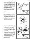
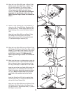
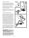
17. Locate the Long Cable (80). Insert one end of
the Cable through the welded tube on the indicat-
ed end of the Cross Tube (11) and then through a
Swivel Arm (22). If necessary, use the tip of a
screwdriver to pull the end of the Cable out of the
Swivel Arm.
Be sure the Cable is on the indicat-
ed side of the welded rod in the Swivel Arm.
Insert the Swivel Arm (22) into the welded tube
on the Cross Tube (11). Secure the Swivel Arm
with an M4 x 5mm Screw (104).
Wrap the Long Cable (80) around a 90mm Pulley
(28). Attach the Pulley inside of the Swivel Arm
(22) with an M10 x 42mm Button Bolt (71) and an
M10 Nylon Locknut (76).
17
71
22
104
28
80
11
76
Rod
“U”-Channel
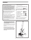
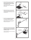
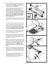
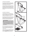
16. Locate the Fulcrum (18) on the Lat Tower (4) (see
t
he inset drawing). Slide the Tray (35) onto the
rods on the Fulcrum.
Make sure the Tray is ori-
ented as shown in the drawing.
S
et the resistance bars into the Tray (35) in the
f
ollowing order: the 10-pound Removable
Resistance Bar (67), the 20-pound Removable
Resistance Bar (36), an 80-pound Resistance Bar
(95), the 10-pound Center Resistance Bar (44), an
80-pound Resistance Bar (95), and the 40-pound
Resistance Bar (96).
Make sure the indicated
rings are on the side shown and the arrows
point toward the Tray.
Attach the Cover Plate (72), with the edges up, to
the Tray (35) with two M8 x 19mm Button Screws
(86).
18
76
110
110
75
80
73
29
28