


3 4
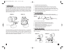
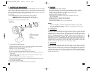
AC AND DC RECHARGE ADAPTERS
FIGURE 2A FIGURE 2B
4.1 AC RECHARGE
The AC Recharge adapter provides 300 mA DC for recharging the
batteries. Power the AC Recharger from a standard, 120 volt, 60 Hz AC North
American receptacle. The AC recharger will not support lamp operation. Do not
operate the lamps while the AC Recharger is connected to the Recharge Port.
Charge with lamps Off until LEDs are equally bright. This steady recharge will
prolong battery life. Only use the supplied AC Recharger—DO NOT SUBSTITUTE
WITH ANOTHER. (SEE FIGURE 2A)
4.2 DC RECHARGE DC
The Recharge adapter provides DC for recharging the batteries.
Power the DC Recharger from a standard, 12 volt DC cigarette lighter type
accessory socket. Charge until LEDs are equally bright. Only use the supplied
DC Recharger - do not substitute with another. The DC Recharge Adapter’s DC Plug
is equipped with a user-replaceable 10-ampere fuse. (SEE FIGURE 2B)
5. MAINTENANCE/PARTS REPLACEMENT
If the unit has dirt on it, gently clean the outer surfaces of the Sport Spot Lantern
with a soft cloth moistened with a mild solution of water and detergent. Periodically
inspect the condition of recharge adapters, connectors and wires. Replace any
components that may have become worn or broken.
Four parts are replaceable by users. The quartz halogen bulb and the fluorescent
tube are proprietary and are only available through Vector Manufacturing. The sealed
lead acid battery and fuse are available from Vector as well as from popular
automotive parts suppliers nationwide. Contact Technical Support for replacement parts
and any additional information that you may need at (866) 584-5504.
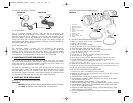
6. SPOTLIGHT BULB REPLACEMENT
See Figure 3 for bulb removal and replacement.
WARNING:
DO NOT ATTEMPT SPOTLIGHT BULB REPLACEMENT UNLESS POWER IS
OFF AND THE BATTERY IS DISCONNECTED. SEE SECTION 9.
DC RECHARGE
ADAPTER
FUSED DC PLUG
BARREL CONNECTOR
AC RECHARGE
ADAPTER
1. SAFETY RING
2. RETAINING RING TAB
3. RETAINING RING LENS
4. LENS
5. O-RING
6. REFLECTOR/LAMP ASSEMBLY
7. NOTCH
8. RETAINING WIRES
9. WHITE WIRE
10. GREEN OR BLACK WIRE
11. SCREW
2
3
4
1
7
65
8
9
10
11
11
9
10
SPOTLIGHT BULB REMOVAL/INSTALLATION
FIGURE 3
6.1 SPOTLIGHT BULB REMOVAL PROCEDURE
1. Make sure that the Power Switch is Off AND the
battery is disconnected.
2. Rest the unit on a secure tabletop.
3. Position the head to be in the Spotlight position.
4. Lift off the rubber Safety Ring and set it aside.
5. Grasp the Retaining Ring and rotate it slightly clockwise until the
ring’s tab lines up with the notch in the head.
6. Lift off the retaining ring.
7. Pull the lens, “O” ring and reflector assembly from the head.
8. Set the lens and “O” ring aside.
9. The Reflector/Lamp Assembly should be hanging from the two wires.
10. On the Reflector Assembly, carefully squeeze the two retaining wires
together and lift them to release them from the “T” slot.
11. Loosen the screw—item #11.
12. Rotate the two retaining wires upward as shown, to allow the bulb to lift out.
13. Disconnect the white wire by pulling apart the two connectors on the wire.
14. Follow local procedures for bulb disposal.
6.2 SPOTLIGHT BULB INSTALLATION PROCEDURE
1. Insert the new bulb in the Reflector/Lamp Assembly.
2. Rotate the two retaining wires downward as shown, to hold the bulb in place.
3. Tighten the screw— item #11.
4. Connect the white wire by pushing together the two connectors.
5. On the reflector Assembly, carefully squeeze the two retaining wires together
and place them in the “T” slot.
6. Replace the Reflector/Lamp Assembly, “O” Ring and Lens.
7. Place the Retaining Ring so that it’s tabs are aligned with the notches in the head.
8. Press the Retaining Ring until it is fully seated and rotate it slightly counter clock–
wise to secure it against the head.
9. Replace the rubber Safety Ring by pushing it onto the Retaining Ring. Make
sure the Safety Ring is fully seated.
10. Check the spotlight operation by reconnecting the battery and turning on
the switch.
VEC128SL_ManualEN_092605 9/26/05 9:20 AM Page 11