


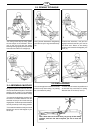

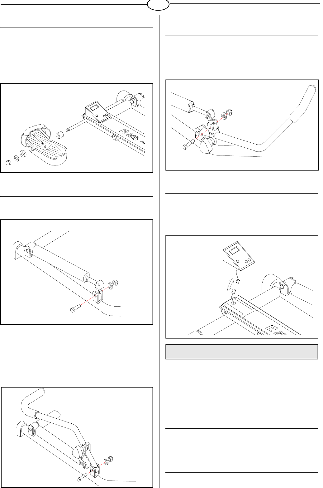
1.4. OAR BRAKE (SHOCK ABSORBER)
ASSEMBLY
Insert the end of the brake in the aluminium clamp, push the bolt
through the clamp and the sleeve and tighten the nut holding the
bolt in place with an open-end wrench (fig. 7). Make sure that
the resistance adjustment knob is facing outwards. Fasten the
other oar brake in the same manner.
1.5 METER ASSEMBLY
Insert two 1,5 V AA-batteries by opening the bottom of the
meter cover.Replace the top cover and connect the meter
cable with the transmitter cable Thread the cables into the
groove in the rail to avoid damage. The meter is fastened to the
rail with two straps of adhesive fabric (fig. 8).
2. USE
Rowing is a very effective form of exercise. In addition to
strengthening the heart and improving circulation, it develops
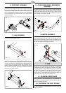
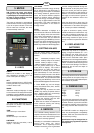
1.2. FOOTREST ASSEMBLY
Remove the nut and the thin metallic and plastic washers from
the footrest shaft. Install a footrest on the shaft so that the thick
plastic washer stays between the footrest and the frame. Place
the plastic and metallic washers and a nut at the end of the shaft
(fig. 4). Install the other footrest in the same way. Tighten both
nuts simultaneously by holding the other nut in place with an
open end wrench.
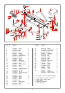
1.3. OAR ASSEMBLY
Remove the screw shown in fig. 5.
Remove the plastic cover on the bearing housing of the oar.
Make sure that the sleeve bearing remains inside the bearing
housing. To install the oar, place its lower end in the oar bracket,
push the screw through the bracket and the sleeve (fig. 6).
Insert the washer and tighten the nut, holding the bolt in place
with an open-end wrench. Tighten the screw hard. Install the
other oar in the same manner.
the various groups of large muscles: the back, the abdomen,
the arms, the shoulders as well as the pelvis and the legs.
Rowing also develops muscular flexibility without exertion of
joints, and it is a recommended form of exercise for those who
suffer from pains in the neck and shoulder area.
2.1. ADJUSTING RESISTANCE
With the adjuster in the lowest position (1), the resistance is at
a minimum, in the highest position (5) at its maximum. Do not
tighten the adjuster too hard.
2.2. TIGHTENING THE FOOT STRAPS
Pull the foot straps to correct tightness, turn over the end of the
strap and fasten it.
3
FIG. 6
FIG. 5
GB
FIG. 7
FIG. 4
FIG. 8