


4 ::
:: 5
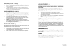
ADJUSTMENTS ::
SETTING THE SEAT HEIGHT AND CORRECT EXERCISING
POSITION
The seat height should be set so that the heal of the foot reaches the
pedal with the leg straight and the pedal at its lowest point. To raise or
lower the seat:
:: First turn the locking knob one turn counter-clockwise.
:: Then pull the locking knob outwards, so that the seat tube can be
moved freely up and down.
:: Once the height is right, let go of the knob and the seat locks into
place.
:: Turn the locking knob clockwise to tighten.
NOTE! Always make sure that the locking knob is properly fastened
before starting to exercise!
The scale on the seat tube helps you remember the seat height that suits
you best. The seat can be inclined forward or backward by turning the
green adjustment ring below the saddle. The seat inclines forward when
the ring is turned clockwise, and back when the ring is turned counter-
clockwise. Do not try to adjust seat inclination when you’re sitting on the
seat - the ring won’t turn.
HANDLEBAR SET-UP
Loosen the grey knob in front of the handlebar and adjust the handlebar
position until your training position feels comfortable. Tighten the grey
knob carefully.
PEDALS
Select strap tightness, set the appropriate strap hole on the retainer from
below and pull forcibly upward. Especially when the equipment is new,
the strap fastening may seem relatively tight.
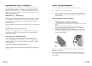
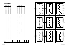
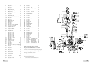
SUPPORTS (FIGURES 2 AND 3)
:: Place the rear support under the frame and fasten it with two hex
screws and washers.
:: Tilt the cycle back so that it rests on the rear support and seat.
Push the plastic covers into place at the ends of the front support.
Turn the cycle back to upright position.
HANDLEBAR (FIGURES 4 AND 5)
:: Expose the wire coming from the frame tube by unwrapping the
tape that covers it, and then connect it to the counterpart in the
handlebar support tube. Ensure that the joint is securely locked by
gently pulling the wire.
:: Thread the wire carefully inside the frame tube and push the
handlebar support tube into place inside the frame tube, so that
the fastening screws are on the front of the tube.
:: NOTE! Use the enclosed Allen key to tighten both fastening
screws through the holes in the tube. Tighten the fastening screws
by turning them counter-clockwise.
:: Remove the protecting fi lm from the display.
POWER CORD (FIGURE 6)
Plug the transformer into the connector, just above the rear support, and
then the transformer cord into the wall socket.
:: Always unplug the appliance from the wall socket and remove the
cord from the appliance immediately after use.
:: Make sure that the cord does not run underneath the appliance.