7
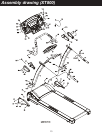
ASSEMBLY (XT600)
It will take two people to assemble your unit.
STEP 1
Remove all the components from the carton.
STEP 2
Remove the bottom side covers that are pre-assembled on the frame.
Connect the computer extension wire (50) to the lower computer wire (49).
NOTE: Ensure that the wire is safely inserted in the upright to avoid pinching the computer wire.
STEP 3
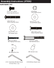
Insert the right upright (4) into the frame base (2) through the bottom right side cover (64). Secure the
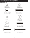
reaming holes with four 5/16” x 15mm button head bolts (138) and one tooth washer (145) on the top hole
of the side upright using the combination wrench / screwdriver (141).
Repeat for left side.
HAND TIGHTEN ONLY FOR NOW.
STEP 4
Install the Handgrip Tubes (7A / 7B) into the Left and Right Uprights (4 / 5). Secure using four 5/16” x 2”
button head bolts (134) and four curved washers (140) using the Combination M5 Allen Wrench &
Screwdriver (141). HAND TIGHTEN ONLY FOR NOW.
Note: the right handgrip tube has the fast and slow button and the left handgrip tube has the up and down
button.
STEP 5
Install the inside right handgrip side cover (69) to the console mounting bracket of the right upright (4).
Ensure that the wiring is fed through the end of the caps.
Install the inside left handgrip side cover (68) to the console mounting bracket of the left upright (5).
Ensure that the wiring is fed through the end of the caps.
Install the console assembly (52) into the mounting brackets of the right and left uprights (4 / 5).
NOTE: Carefully insert the wires inside the console assembly, so that you do not pinch and cut
the wires when fastening the console assembly.
Secure the top of the console mounting tube with two hex head bolts 5/16” x 2-3/4” (93) and two flat
washers (139) using the combination wrench / screwdriver (141). Secure the top of the console mounting
tube with two 5/16” x 1-1/2” button head bolt (137), two flat washers (139) and two tooth washers (145)
using the combination wrench / screwdriver (141).
Connect the computer extension wire (50) to the upper computer extension wire (48).
Connect the speed adj. switch w/cable (56) to the upper speed cable (37).
Connect the incline adj. switch w/cable (57) to the upper incline cable (38).
Install the outside right handgrip side cover (70) to the console mounting bracket of the right upright (4).
Secure the handgrip side covers (69 / 70) using three 3.4 x 40mm self tapping screw (135).
Install the outside left handgrip side cover (67) to the console mounting bracket of the left upright (5).
Secure the handgrip side covers (67 / 68) using three 3.4 x 40mm self tapping screw (135).
HAND TIGHTEN ONLY FOR NOW.
STEP 6
Secure the bottom right side cover (64) onto the frame base (2). Secure using three 5x16mm tapping
screw (120) which you have previously removed.
Repeat for the left upright cover (63).
A
ttach the two bolt access caps (146) onto the handgrip side caps (67 / 68, 69 / 70).
ENSURE THAT ALL NUTS AND BOLTS ARE NOW FIRMLY TIGHTEN.


