11
ASSEMBLY (XT800)
Assembly
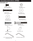
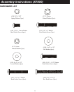
Unpack the treadmill and locate the hardware pack. The hardware pack is separated into: one section
containing tools and four sections labeled steps 1- 4 which contain the hardware needed for assembly
of each step. The assembly steps below are numbered one through four and correspond to the
hardware in the numbered sections of the hardware pack. Remove only the hardware for the step you
are currently assembling to avoid confusion and mix-ups.
STEP 1
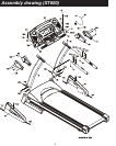
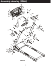
1. Take the Right Handrail (4) and connect the Computer Cable (middle) (33) that exits from the
bottom of the tube, with the Computer Cable (lower)(32). Install the Left and Right Handrails
into the Left and Right Receiving Tubes of Main Frame (1). Be careful not to pinch the wire
when installing the Handrail.
2. Install and hand tighten the 2pcs of 3/8” x 2” Button Head Socket Screws (103), 2pcs of 3/8" x
2.0T Spring Washers (108) and 2 pcs of 10 m/m Raised Washers (122) into the top hole on the
sides of the L & R Handrails (4,5). Then install and hand tighten the 6pcs of 5/16”x 15m/m
Button Head Socket Screws (102) in the remaining holes on the sides and front of the L & R
Handrails (4,5) by using the Combination M5 Allen Wrench & Screwdriver (111) and M6 Allen
Wrench (112).
Do not tighten these screws until assembly is complete.
STEP 2
1. Install the L & R Handgrip Side Caps (53,54) onto the ends of the console mounting tube.
Ensure the Handgrip Side Caps (53,54) are oriented correctly and facing the correct direction
(see diagram). Also ensure that the wiring is fed through the Handgrip Side Caps (53,54).
Place the console onto the L & R mounting brackets at the top of the Handrails (4,5). Then
install and hand tighten the 2 pcs of 5/16” x 2-3/4” Hex Head Screws (105) and 8 x 23 x 1.5T
Flat Washers (109) through the hole in the top of the console mounting tube and the 2 pcs of
5/16” x 1-1/2” Button Head Socket Screws (106), 8 x 23 x 1.5T Flat Washers (109) and 2 pcs
of 8 m/m Raised Washers (121) by using the Combination M5 Allen Wrench & Screwdriver (111)
and 12m/m Wrench (113) through the hole in the front of the console mounting tube.
2. Mount the L&R Handgrip(8A, 8B) onto Handgrip mounting plates at the top of the Handrails
(4,5) with 4pcs of 5/16” x 2” Button Head Socket Screws (101) and 4pcs of 8 x 23 x 1.5T
Curved Washers(110) by using the Combination M5 Allen Wrench & Screwdriver (111).
NOTE: The L&R Handgrips (8A, 8B) are different. The Right Handgrip (8A) has two
wires and the switches on the handle bar say “Fast and Slow ” while the Left Handgrip
(8B) say “Up and Down”.


