


5
6
17
17
71
71
21
21
4
5
Front
Rear
Sheath
Side
1
1
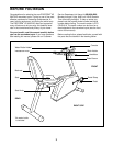
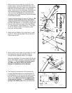
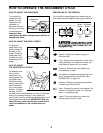
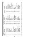
1. While another person holds the Upright (6) in the
position shown, connect the Extension Wire (18) to
the Reed Switch Wire (20). Refer to the inset drawing.
Make sure that the plastic sheath is in the location
shown. Insert the tip of the Resistance Cable (22) into
the indicated opening in the Cable Connector (69).
Then, pull up on the Resistance Cable and insert it
into the top of the Cable Connector. Center the sheath
on the Cable Connector.
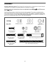
Carefully slide the Upright (6) onto the Frame (1). Be
careful to avoid pinching the wires and cables.
Loosely thread four M10 x 25mm Button Screws (71)
with M10 Split Washers (17) through the Upright and
into the Frame. Secure the tops of the Side Shields
(4, 5) with two M4 x 16mm Screws (21). Firmly tight-
en the four Button Screws in the following order:
front, rear, and then sides.
16
18
Hole
Hole
33
6
3
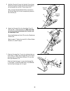
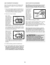
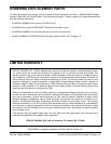
3. While another person holds the Handlebar (16) near
the Upright (6), route the Pulse Wires (33) up
through the two indicated holes in the Upright.
Attach the Handlebar (16) to the Upright (6) with two
M10 x 25mm Button Screws (71) and two M10 Split
Washers (17). Do not tighten the Button Screws
yet. Make sure that no wires are pinched
between the Handlebar and the Upright.
71
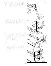
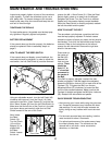
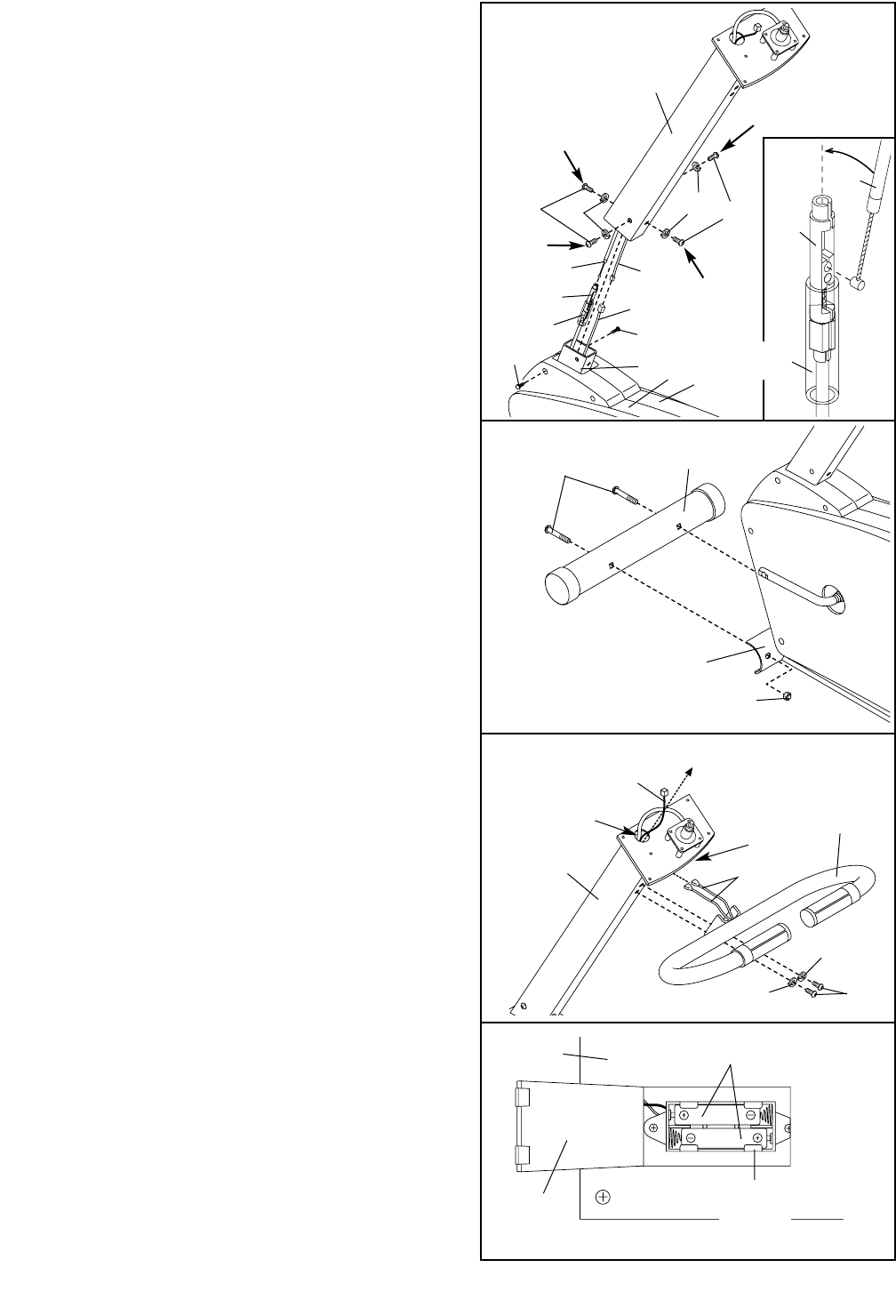
4. The Console (9) requires two “AA” batteries (not
included). Alkaline batteries are recommended. To
install batteries, turn the console over, open the bat-
tery door, and insert two batteries into the battery
clip as shown. Make sure that the negative ends
of the batteries (marked “—”) are touching the
springs in the battery clip. Close the battery door.
4
Battery
Door
Battery
Clip
Batteries
9
17
17
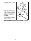
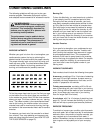
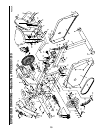
2. Attach the Front Stabilizer (2) to the Frame (1) with
two M10 x 75mm Carriage Bolts (72) and two M10
Nylon Locknuts (45).
2
1
72
45
2
Side
18
20
22
22
69
69
Sheath