


5
ASSEMBLY
To hire an authorized service technician to assemble the exercise cycle, call toll-free 1-800-445-2480.
Assembly requires two persons. Place all parts of the exercise cycle in a cleared area and remove the packing
materials. Do not dispose of the packing materials until assembly is completed. Assembly requires the included
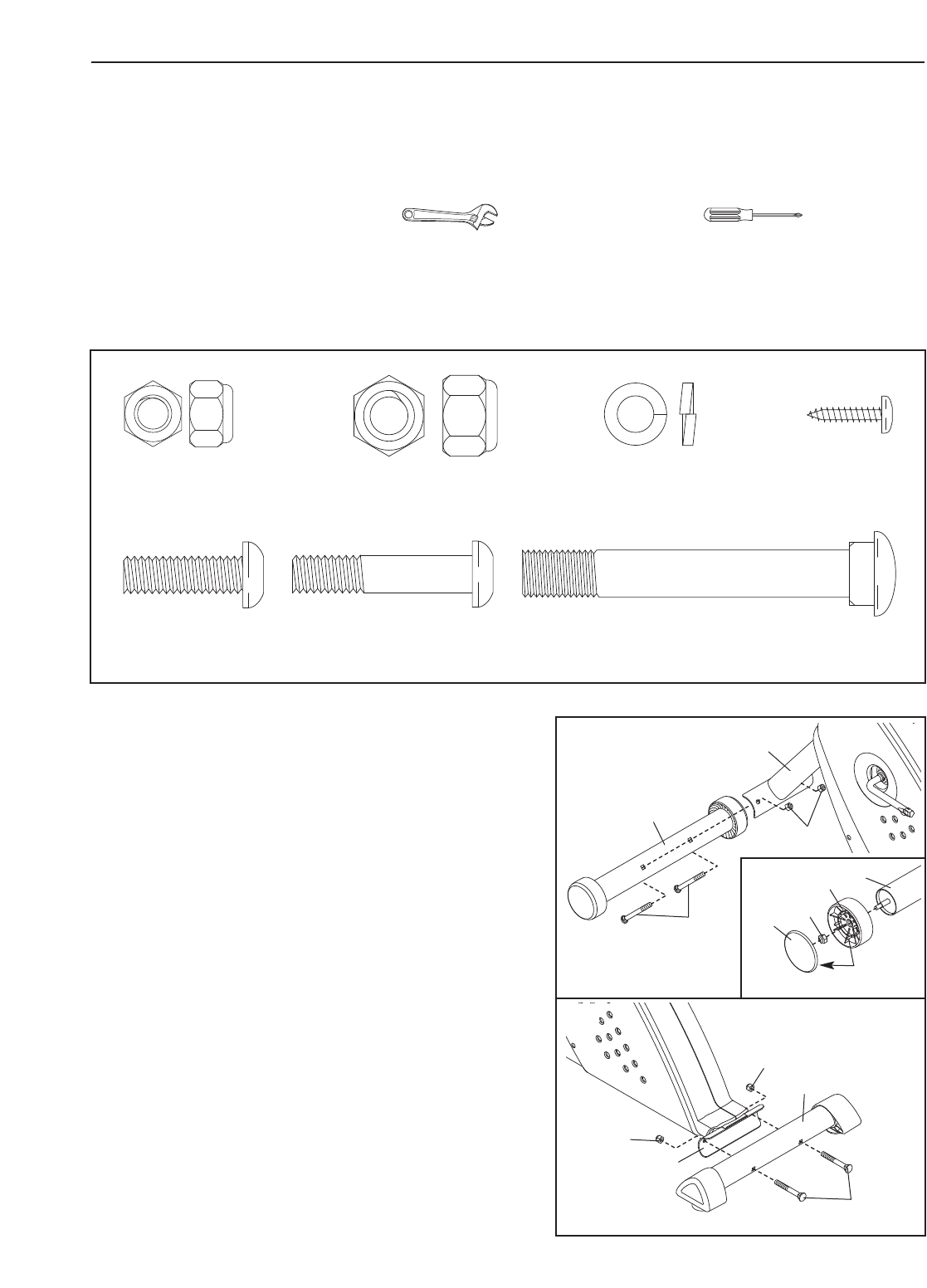
tools and your own adjustable wrench and Phillips screwdriver .
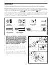
Use the drawings below to identify the small parts needed for assembly. The number in parentheses below each
drawing is the key number of the part, from the PART LIST on page 18. The number following the key number is
the quantity needed for assembly.
Note: Some small parts may have been preassembled. If a part is not in
the parts bag, check to see if it has been preassembled.
M8 Nylon
Locknut (10)–6
G
M8 Split Washer
(41)–10
M10 Nylon
Locknut (33)–4
M4 x 16mm
Screw (49)–4
M8 x 25mm Button
Screw (45)–6
M10 x 75mm Carriage Bolt (30)–4
M8 x 38mm Button
Screw (9)–2
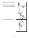
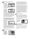
1. Identify the Front Stabilizer (2). See the inset drawing.
Attach a Wheel (14) to one end of the Front Stabilizer
with an M8 Nylon Locknut (10). Make sure that the
Wheel is oriented as shown and that it turns freely.
Next, align the four plastic posts on a Wheel Cover
(23) with the plastic posts on the Wheel, and press the
Wheel Cover onto the Wheel. Assemble the other
Wheel (not shown) in the same way
.
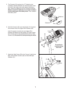
While another person lifts the front of the Frame (1),
attach the Front Stabilizer (2) to the Frame with two
M10 x 75mm Carriage Bolts (30) and two M10 Nylon
Locknuts (33) as shown.
2
33
30
1
1
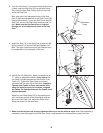
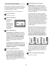
2. While another person lifts the rear of the Frame (1),
attach the Rear Stabilizer (6) with two M10 x 75mm
Carriage Bolts (30) and two M10 Nylon Locknuts (33).
30
6
1
33
33
2
2
14
23
10
Post