


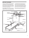
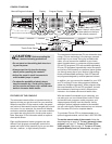
7. Make sure that all parts are tightened before you use the treadmill. Keep the included allen wrench in a
secure place. The allen wrench is used to adjust the walking belt (see page 21). To protect the floor or carpet
from damage, place a mat under the treadmill.
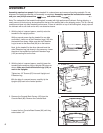
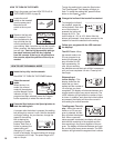
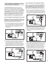
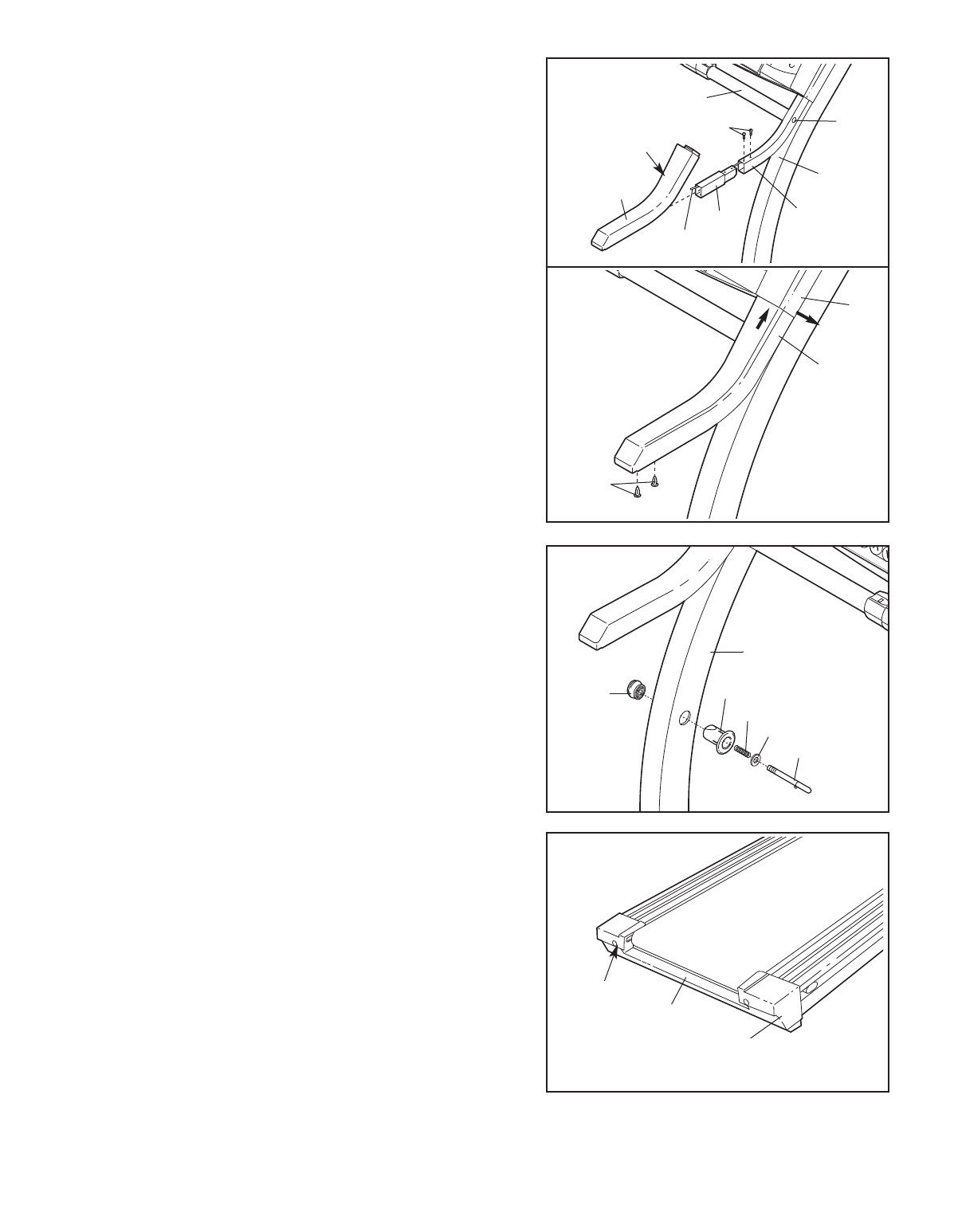
4. Using the included allen wrench, tighten the Pulse Bar
Bolt (78) on each side of the treadmill.
Find the plastic tie inside the post on the right Upright (69).
I
nsert the plastic tie through the Handrail Extension (66)
and insert the Handrail Extension into the post as shown.
Tap the Handrail Extension with a rubber mallet to fully in-
sert it. Attach the Handrail Extension with two Handrail
Extension Screws (67) as shown. Slide the Right Foam Grip
(75) as far as possible onto the post. Note: The Right Foam
Grip has a cutout in the left side for the Pulse Bar (76).
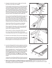
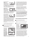
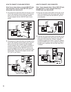
Lift up on the Console Base (82) and slide the upper end
of the Right Foam Grip (75) under the Console Base.
Note: Pull out on the side of the Console Base (arrow A)
as you slide the Foam Grip under it. Press the Console
Base down over the ridge on the Foam Grip. Press two
Fasteners (49) into the underside of the Right Foam Grip.
Attach the Left Foam Grip (not shown) as described
above. Note: There is no plastic tie in the left side.
Refer to step 3b. Press down on the Console Base (82)
as you tighten the four Console Base Screws (80). Be
careful not to overtighten the Screws.
Refer to step 3a. Hold the Console Back (88) in the posi-
tion shown. Attach the Console Back with the eight
Console Back Screws (83). Do not overtighten the Screws.
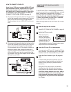
5. Press the Lock Knob Sleeve (70) into the left Upright (69).
Make sure that the Lock Pin Collar (72) and the Spring (71)
are on the Lock Pin. Insert the Lock Pin into the left Upright
(69) and tighten the Lock Knob (68) onto the Lock Pin.
69
70
68
71
72
74
5
75
7
6
C
utout
Tie
66
Post
67
69
7
8
4a
49
75
A
82
4b
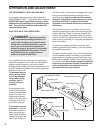
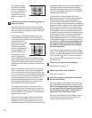
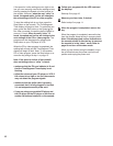
6.
Look at the Endcap (58). If the left or right foot on the End-
cap does not touch the floor, the included thick base pads
should be attached to the treadmill as described below.
Refer to assembly step 2. Lower the treadmill frame and
the Uprights (69) as shown. If the left foot of the Endcap
(58) was off the ground, remove the two Base Pads (99)
from the right Upright (69). Attach the included thick
base pads to the Upright. If the right side of the Endcap
was off the ground, attach the thick base pads to the left
Upright.
If either side of the Endcap (58) lifts off the floor when the
treadmill is used, attach the thick base pads as described.
58
6
7
Foot
Foot