


512
Inspect and tighten all parts of the exercise cycle reg-
ularly. The exercise cycle can be cleaned with a soft,
damp cloth. To prevent damage to the console, keep
liquids away and keep the console out of direct sun-
light.
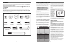
BATTERY REPLACEMENT
If the console does not function properly, the batteries
should be replaced. To replace the batteries, refer to
assembly step 12 on page 7.
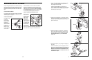
CRANK ADJUSTMENT
If the arms of the
Crank (29)
become loose,
they should be
tightened in
order to prevent
excessive wear.
Loosen the
crank nut on the
left arm of the
Crank. Place the
end of a stan-
dard screwdriver in one of the slots in the slotted
bearing nut. Lightly tap the screwdriver with a ham-
mer to turn the slotted bearing nut counterclockwise
until the arms are no longer loose. Do not overtight-
en the slotted bearing nut. When the slotted bearing
nut is properly tightened, tighten the crank cut.
HOW TO STORE THE EXERCISE CYCLE
When the exer-
cise cycle is not
in use, it can be
folded for com-
pact storage.
Refer to the
drawing at the
right. Loosen the
Lock Knob (68)
on the right side
of the Frame (1).
Slide the Seat
Frame (3) as far
into the Frame
as it will go. Tighten the Lock Knob. Store the exer-
cise cycle indoors, away from moisture and dust.
MAINTENANCE AND STORAGE
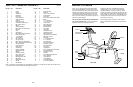
Crank
Nut
Slotted
Bearing
Nut
29
68
3
1
68
1
3
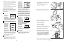
72
72
72
76
75
1
Wheels
74
1
1. Loosen the Lock Knob (68) on the right side of the
Frame (1). Slide the Seat Frame (3) out until it
stops. Tighten the Lock Knob.
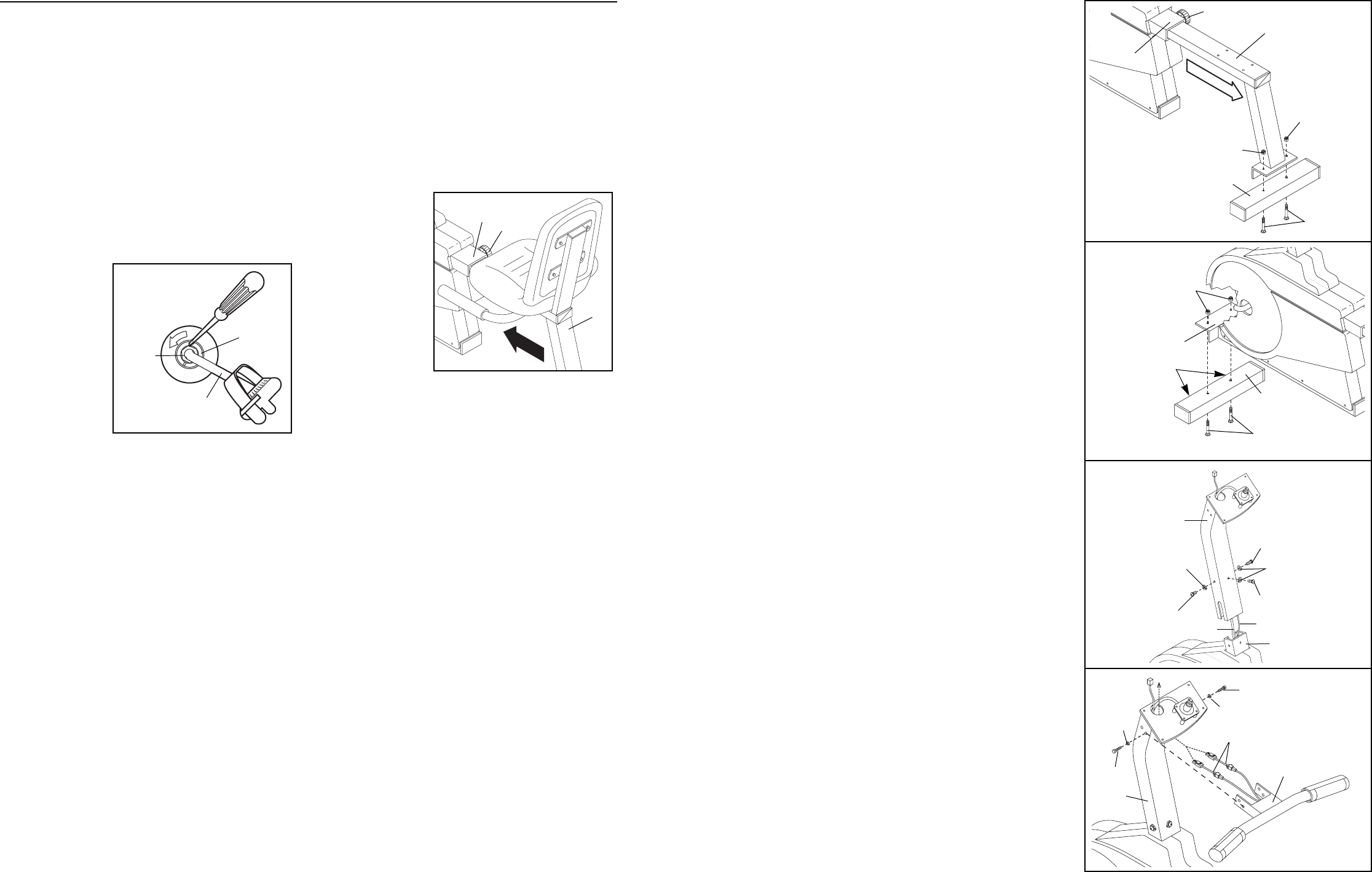
Identify the Rear Stabilizer (76), which has no
wheels. Attach the Rear Stabilizer to the Seat Frame
(3) with two M10 x 58mm Carriage Bolts (74) and
two M10 Nylon Locknuts (72).
2. Identify the Front Stabilizer (75), which has wheels.
Attach the Front Stabilizer (75) to the Frame (1) with
two M10 x 58mm Carriage Bolts (74) and two M10
Nylon Locknuts (72).
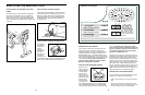
3. Attach the Upright (2) to the Frame (1) with three
M10 x 25mm Button Head Screws (25) and three
M10 Split Washers (26). Be careful not to pinch
the Reed Switch Wire (13) or the Resistance
Cable (10).
4. Route both Adapters (73) up through the Upright (2)
as shown.
Attach the Handlebar (4) to the Upright (2) with two
M6 x 25mm Hex Head Screws (14) and two M6 Split
Washers (67), but do not tighten the Screws yet.
Make sure that the Screws are threaded into the
indicated holes. Note: Two additional Screws will
be attached in step 6.
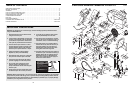
3
2
26
26
25
25
25
1
10
13
4
73
2
14
14
67
67
4
2
74