


5
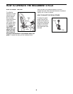
ASSEMBLY
Assembly requires two persons. Place all parts of the recumbent cycle in a cleared area and remove the pack-
ing materials. Do not dispose of the packing materials until assembly is completed. In addition to the included
tools, assembly requires an adjustable wrench and a Phillips screwdriver .
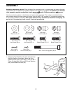
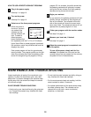
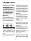
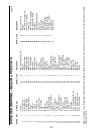
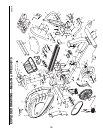
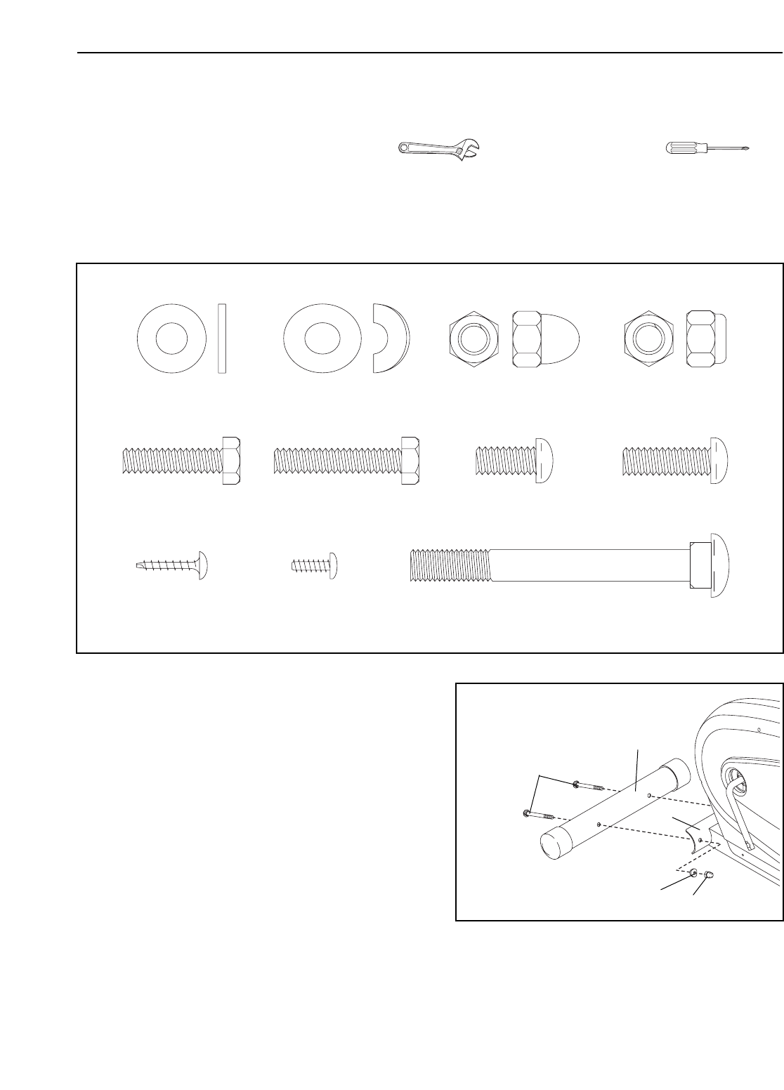
Use the part drawings below to identify the small parts used in assembly. The number in parenthesis below
each drawing refers to the key number of the part, from the PART LIST on page 14. The second number refers
to the quantity needed for assembly. Note: Some small parts may have been pre-attached for shipping. If a
part is not in the parts bag, check to see if it has been pre-attached.
M8 x 70mm Carriage Bolt (66)–4
M8 Flat
Washer (18)–12
M8 Curved
Washer (28)–8
M8 Nylon
Locknut (35)–4
M4 x 8mm
Ground Screw (63)–1
M8 Nylon
Locknut (56)–4
M6 x 25mm
Hex Screw (29)–4
M6 x 38mm
Hex Screw (67)–4
M8 x 15mm
Button Screw (27)–12
M8 x 20mm
Button Screw (31)–4
M4 x 16mm
Screw (54)—4
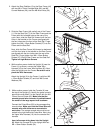
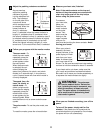
1. Identify the Front Stabilizer (2), which is shorter than
the Rear Stabilizer (not shown). Attach the Front
Stabilizer to the front of the Frame (1) with two M8 x
70mm Carriage Bolts (66), two M8 Curved Washers
(28), and two M8 Acorn Nuts (56).
2
1
28
66
56
1