


6
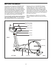
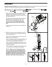
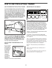
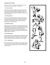
2. While another person holds the Upright (3) near the
Frame (1) as shown, connect the Extension Wire (63)
to the Sensor Wire (25).
Next, connect the Resistance Cable (26) to the Lower
Cable (64) in the following way:
¥ Refer to drawing A. Pull up on the metal bracket, and
insert the tip of the Resistance Cable (26) into the
wire clip on the Lower Cable (64) as shown.
¥ Refer to drawing B. Firmly pull the Resistance Cable
(26) and slide it into the metal bracket on the Lower
Cable (64) as shown.
¥ Refer to drawing C. Using pliers, squeeze the prongs
on the upper end of the metal bracket together.
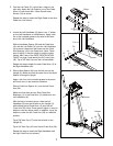
Slide the Upright (3) onto the welded bolts on the
Frame (1). Make sure that the Resistance Cable
(26) doesnÕt become caught on the Frame (1) or
the Upright (3). Be careful to avoid pinching the
Resistance Cable (26) and the Sensor Wire (25)
between the the Frame and the Upright. Tighten an
M10 Nylon Locknut (29) onto each welded bolt.
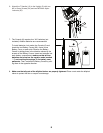
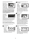
1. While another person holds the Console (6) near the
Upright (3), insert the Resistance Cable (26) down
through the Upright. Next, connect the console wire to
the Extension Wire (63).
Feed the slack Resistance Cable (26) and Extension
Wire (63) down into the Upright (3). Attach the
Console (6) to the Upright with four M4 x 16mm
Round Head Screws (38). Be careful to avoid
pinching the Resistance Cable and the Sensor
Wire.
Press the Resistance Knob (50) onto the Resistance
Cable (26).
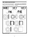
ASSEMBLY
Assembly requires two people. Place all parts of the elliptical trainer in a cleared area and remove the packing
materials. Do not dispose of the packing materials until assembly is completed.
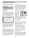
Assembly requires that you have a phillips screwdriver , two adjustable wrenches , a
rubber mallet , and a pair pliers .
1
6
3
38
26
63
Console
Wire
50
2
64
3
29
26
Welded
Bolts
63
64
25
1
64
26
Metal
Bracket
26
B
A
C
64
26