


7
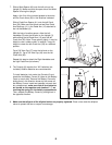
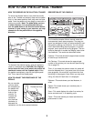
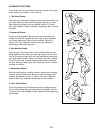
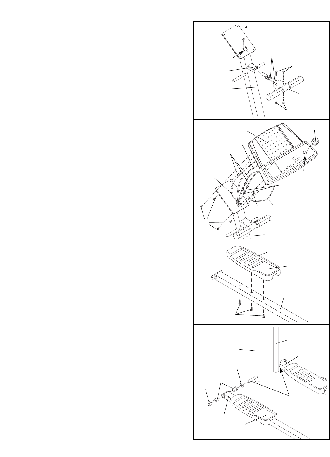
5. Find the Left Pedal (31), which has a ridge on the
right side. Attach the Left Pedal to one of the Pedal
Arms (12) with three M4 x 19mm Round Head
Screws (16) as shown.
Repeat this step to attach the Right Pedal to the other
Pedal Arm (not shown).
6. Locate the Left Handlebar (8) (there is an “L” sticker
on the Left Handlebar for identification). Apply a thin
film of the included grease to the axle at the lower
end of the Left Handlebar.
Slide a Handlebar Spacer (39) and the Pedal Arm
(12) with the Left Pedal (31) onto the Left Handlebar
(8) as shown. Make sure that there are two Pedal
Arm Bushings (11) in the Pedal Arm. (Note: These
parts fit tightly; it may be helpful to use a rubber mal-
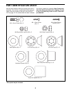
let). Next, refer to the PART IDENTIFICATION
CHART on page 5 and identify the 3/4” Axle Caps
(43). Tap a 3/4” Axle Cap onto the Left Handlebar.
Repeat this step to attach the other Pedal Arm (12) to
the Right Handlebar (62).
5
31
12
16
8
62
43
11
12
12
6
39
Ridge
31
Grease
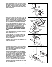
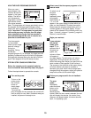
4. While another person holds the Console (6) near the
Upright (3), attach the ground wire to the Upright with
an M4 x 16mm Screw (34). Connect the Extension
Wire (61) to the corresponding console wire. Connect
the pulse wires to the corresponding console wires.
Pull any slack Resistance Cable (26) up out of the
Upright (3) and push it into the Console (6). Feed the
slack Extension Wire (61) down into the Upright.
Attach the Console to the Upright with four M4 x
16mm Screws (34). Be careful to avoid pinching
the wires or pinching or kinking the Resistance
Cable.
Press the Resistance Knob (50) onto the upper end
of the Resistance Cable (26).
4
6
3
Ground
Wire
34
26
34
26
61
Console
Wires
50
3
55
54
Pulse
Wires
Pulse Wires
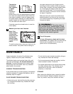
10
3
Bracket
Hole
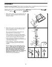
3. Insert the pulse wires beneath the indicated bracket
on the Upright (3) and up out of the hole in the top of
the Upright. Attach the T-Handle (10) to the Upright
with two M6 x 16mm Screws (54) and two M6 Black
Nylon Locknuts (55).