


6
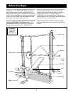
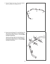
1. Before beginning assembly, make sure you have
read and understand the information in the box
above.
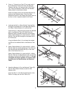
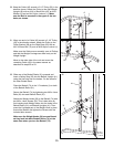
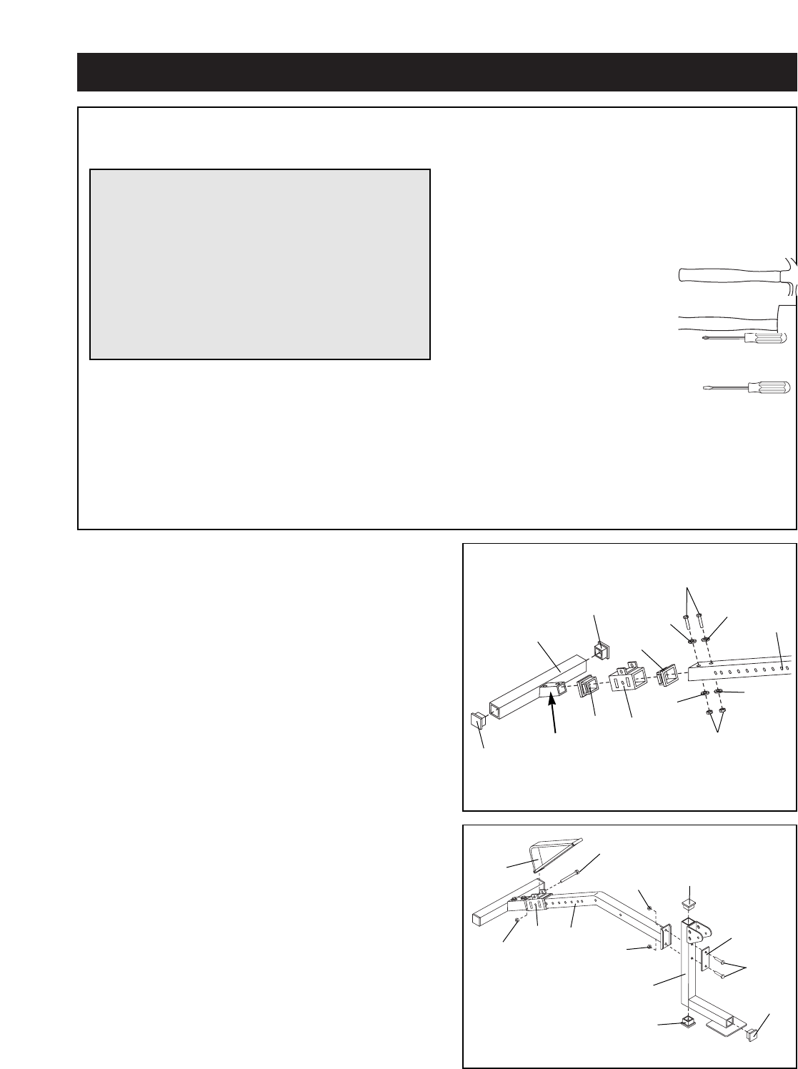
Press a 2Ó Square Inner Cap (17) into each end of
the Stabilizer (20). Press a Carriage Bushing (56) into
each end of the Decline Carriage (44). Slide the
Decline Carriage onto the indicated end of the Frame
(54).
Slide the Frame (54) onto the bracket (A) on the
Stabilizer (20) and secure it with two M10 x 65mm
Bolts (5), four M10 Washers (6) and two M10 Nylon
Locknuts (1). Tighten the Nylon Locknuts until
there is no play between the Frame and Stabilizer.
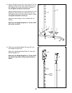
1
Before beginning assembly, carefully read the
following information and instructions:
¥ Assembly requires two people.
¥ Place all parts in a cleared area and remove the
packing materials. Do not dispose of the packing
materials until assembly is completed.
¥ Tighten all parts as you assemble them, unless
instructed to do otherwise.
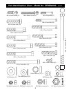
¥ For help identifying the small parts, use the PART
IDENTIFICATION CHART on page 5.
¥ As you assemble the weight bench, make sure all
parts are oriented as shown in the drawings.
The following tools (not included) are required
for assembly:
¥ Two (2) adjustable wrenches
¥ One (1) rubber mallet
¥ One (1) standard screwdriver
¥ One (1) phillips screwdriver
¥ Lubricant, such as grease or petroleum jelly
plus soapy water.
Assembly will be more convenient if you have the
following tools: A socket set, a set of open-end or
closed-end wrenches or a set of ratchet wrenches.
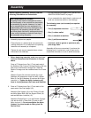
Assembly
Make Things Easier for Yourself!
Everything in this manual is designed to ensure
that the assembly of our products can be complet-
ed successfully by anyone. However, it is impor-
tant to recognize that your new equipment is a
sophisticated product with many small parts and
consequently, the assembly process will take
time. Most people find that by setting aside plenty
of time, and by deciding to make the task enjoy-
able, assembly will go smoothly.
20
56
56
44
17
54
5
6
6
6
6
1
17
A
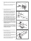
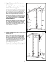
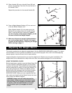
2. Press a 2Ó Square Inner Cap (17) into each of the
open ends of the Pad Upright (19).
Attach the Pad Upright (19) to the Frame (54) with
two M8 x 68mm Bolts (38), the Support Plate (16)
and two M8 Nylon Locknuts (13).
Attach the Decline Strut (11) to the Decline Carriage
(44) with the M10 x 75mm Bolt (72) and an M10
Nylon Locknut (1). Do not overtighten the Nylon
Locknut. You must be able to freely pivot the
Decline Strut.
2
17
38
13
19
13
11
54
44
1
17
72
16
17