


6
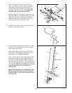
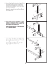
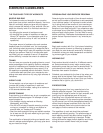
5.
Press four 25mm Square Inner Caps (19) into the
ends of the Backrest Tubes (6).
Attach the Backrest Bracket (10) to the Backrest
Tubes (6) with four M10 x 45mm Button Bolts
(74), four M10 Washers (67), and four M10 Nylon
Locknuts (69).
Make sure the Backrest Tubes
are oriented so that the indicated holes are
closer to the bottom. Do not tighten the
Locknuts yet.
3
4
4
25
73
11
20
72
1
7
17
73
24
7
69
70
75
1
Lubricate
71
1
69
77
75
Lubricate
Handle
Tube
8
5
6
19
67
67
Holes
74
74
69
69
10
19
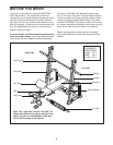
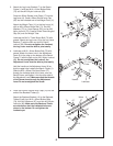
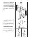
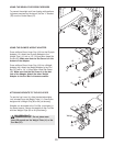
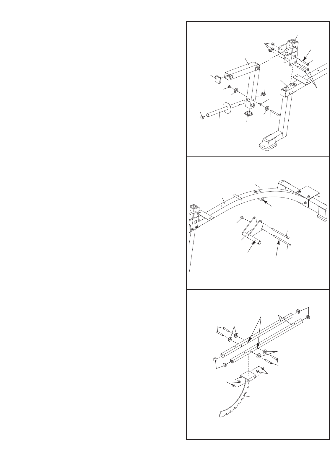
3. Attach the Leg Lever Bracket (7) to the Bench
Frame (1) with two M10 x 81mm Button Bolts
(
75) and two M10 Nylon Locknuts (69).
P
ress two 50mm Square Inner Caps (17) into the
Leg Lever (4). Press a 25mm Round Inner Cap
(20) into the indicated end of the Weight Tube (11).
Attach the Weight Tube (11) to the Leg Lever (4)
with an M8 x 63mm Button Bolt (71), two M8
Washers (73), a 13mm Spacer (25), and an M8
Nylon Locknut (72). Press a 25mm Round Angled
Cap (24) onto the Weight Tube.
Lubricate the M10 x 73mm Button Bolt (70) with
grease. Attach the Leg Lever (4) to the Leg Lever
Bracket (7) with the Bolt and an M10 Nylon
Locknut (69).
Do not overtighten the Locknut;
the Leg Lever must be able to pivot easily.
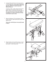
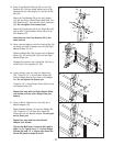
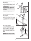
4. Lubricate an M10 x 81mm Button Bolt (75) with
grease. Attach the lower hole in the Adjustment
Lever (8) to the tube on the bottom of the Bench
Frame (1) with the Bolt and an M10 Nylon Locknut
(69). Do not overtighten the Locknut; the
Adjustment Lever must be able to pivot easily.
Hold the handle on the Adjustment Lever (8) so
that the upper hole is above the Bench Frame (1).
Slide the M10 x 65mm Flat Head Screw (77)
through the indicated side of the Lever, over the
Bench Frame, and tighten it into the other side of
the Adjustment Lever. Make sure that the threads
of the Screw show through the Adjustment
Lever. Do not overtighten the Screw.