


5
ASSEMBLY
Assembly requires two persons. Place all parts of the exercise cycle in a cleared area and remove the packing
materials. Do not dispose of the packing materials until assembly is completed.
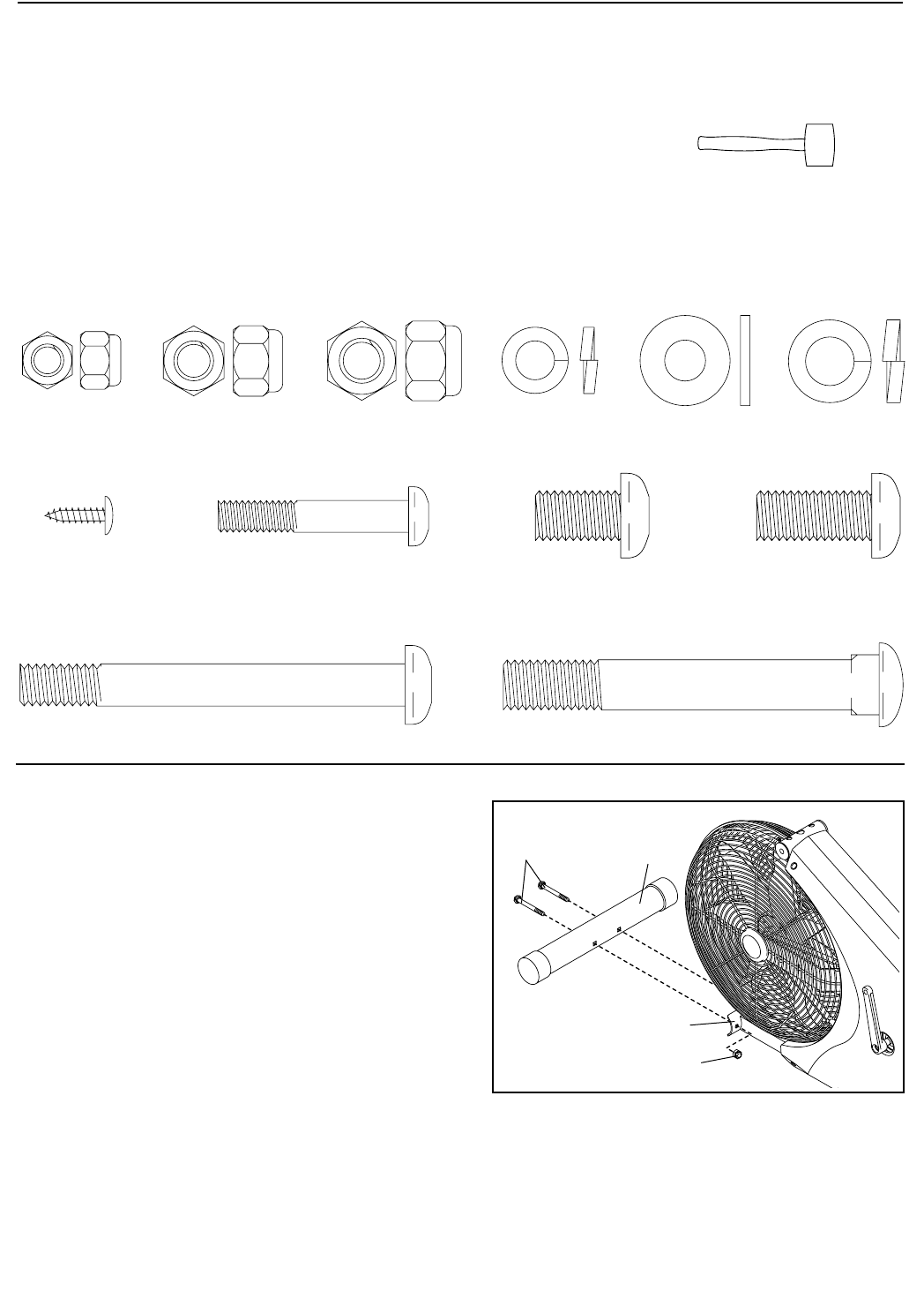
Assembly can be completed using the included tools; however, a rubber mallet is also
recommended.
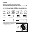
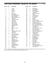
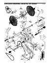
Use the drawings below to identify the small parts used in assembly. The number in parenthesis below each
drawing refers to the key number of the part, from the PART LIST on page 14. The second number refers to the
quantity needed for assembly. Note: Some small parts may have been pre-attached for shipping. If a part is
not in the parts bag, check to see if it has been pre-assembled.
M10 x 75mm Carriage Bolt (65)–4
M4 x 12mm
Screw (77)–2
M8 x 77mm Button Bolt (58)–2
M8 Split
Washer (81)–4
M8 Flat
Washer (73)–4
M6 Nylon
Locknut (56)–4
M8 Nylon
Locknut (66)–6
M10 Nylon
Locknut (64)–4
M10 Split
Washer (54)–12
M6 x 38mm Button
Bolt (57)–4
M10 x 17mm Button
Screw (55)–3
M10 x 22mm Button
Screw (80)–9
65
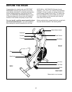
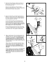
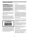
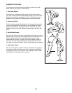
1. Attach one of the Stabilizers (19) to the front of the
Frame (1) with two M10 x 75mm Carriage Bolts (65)
and two M10 Nylon Locknuts (64).
19
64
1
1