


5
ASSEMBLY
To hire an authorized service technician to assemble the exercise cycle, call 1-800-445-2480.
Assembly requires two persons. Place all parts of the exercise cycle in a cleared area and remove the pack-
ing materials. Do not dispose of the packing materials until assembly is completed.
Assembly requires the included tools and your own adjustable wrench and Phillips
screwdriver .
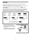
Use the part drawings below to identify the small parts used in assembly. The number in parentheses below
each drawing is the key number of the part, from the PART LIST near the end of this manual. The number fol-
lowing the parentheses is the quantity needed for assembly. Note: Some small parts may have been pre-
assembled. If a part is not in the hardware kit, check to see if it has been preassembled.
M8 x 19mm Button
Screw (77)–4
M8 x 16mm Button
Screw (54)–6
M8 Split
Washer (55)–14
M4 x 16mm
Round Head
Screw (80)–4
M6 Washer
(44)–7
M10 x 63mm Bolt Set (62)–1
M8 x 50mm Button
Screw (52)–4
M6 x 38mm Button
Screw (72)–3
M6 x 42mm Button
Screw (81)–4
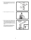
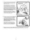
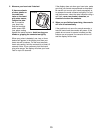
1. Orient the Left Front Stabilizer (15) with the
Wheel (17) positioned as shown. Attach the Left
Front Stabilizer to the left side of the Frame (1) with
three M8 x 16mm Button Screws (54) and three M8
Split Washers (55).
Attach the Right Front Stabilizer (not shown) to
the right side of the Frame (1) in the same way.
15
54
1
1
55
55
54
17