


8
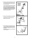
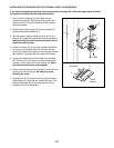
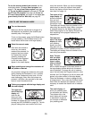
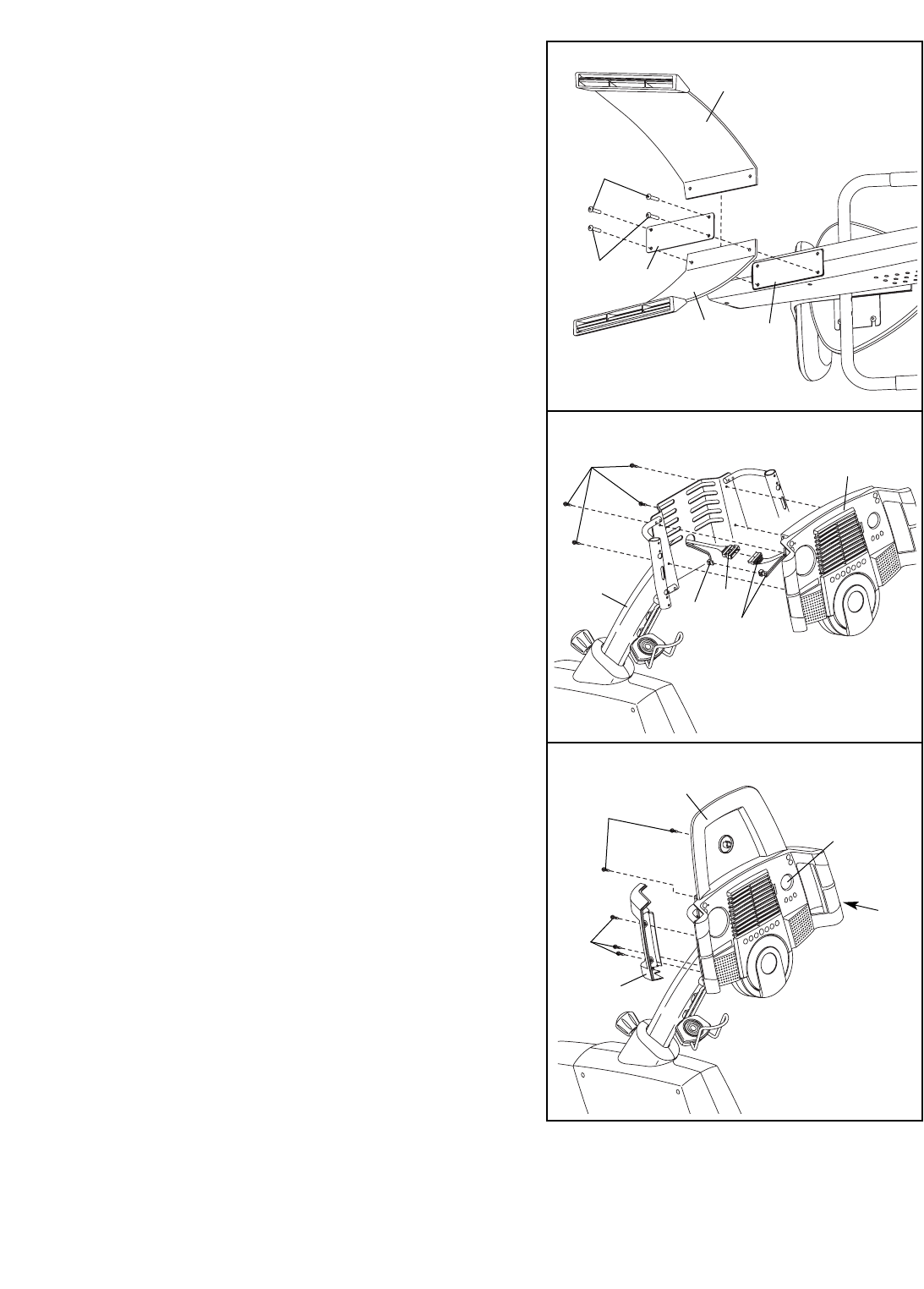
9. See step 10. Remove the three indicated M4 x 12mm
Screws (41) and the Left and Right Handlebar Covers
(6, 5) from the Console (4).
With the help of another person, carefully raise the
exercise cycle so it is resting on the Front and Rear
Stabilisers (not shown).
Whilst another person holds the Console (4) in the
position shown, connect the wire harnesses on the
Console to the Upper Wire Harness (42) and the
Pulse Wire Harness (106). Insert the excess wire har-
ness down into the Upright (2).
Attach the Console (4) to the Upright (2) with four M4
x 12mm Screws (41). Be careful to avoid pinching
the wire harnesses.
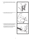
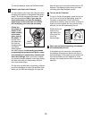
10. Attach the CD Holder (104) to the Console (4) with
two M4 x 12mm Screws (41) as shown.
Attach the Left Handlebar Cover (6) to the Console (4)
with three M4 x 16mm Screws (57).
Attach the Right Handlebar Cover (5) to the
Console (4) in the same way.
9
4
2
41
57
5
4
104
41
6
10
Wire
Harnesses
42
106
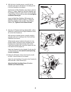
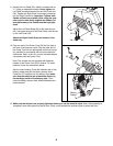
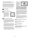
8. With the help of another person, carefully tip the
exercise cycle onto its left side so it is resting on the
Left Inner Handlebar (not shown).
Identify the Left Rear Stabiliser (16), which is marked
with an “L” sticker. Attach the Left Rear Stabiliser and
the Stabiliser Plate (87) to the Frame (1) with two M8
x 25mm Button Screws (40) as shown;
do not tighten
the Button Screws yet.
Insert the Right Rear Stabiliser (98) between the
Stabiliser Plate (87) and the Frame (1). Attach the
Right Rear Stabiliser with two M8 x 25mm Button
Screws (40). Tighten all four Button Screws.
40
87
40
1
8
98
16