


47
Ties
72
6a
6b
42
43
2
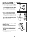
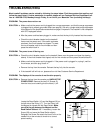
9. Make sure that all parts are properly tightened before you use the treadmill. Note: Extra hardware may
be included. Keep the included allen wrenches in a secure place. The large allen wrench is used to adjust the
walking belt (see page 14). To protect the floor or carpet, place a mat under the treadmill.
47
42
44
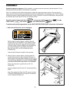
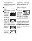
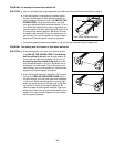
7. Insert the excess Wire Harness (42) into the large hole in
the side of the Right Handrail (72). Securely tighten the
plastic ties on the bottom of the Console Base (47) to
prevent the Wire Harness from slipping.
Then, cut off
the ends of the plastic ties.
Route the Wire Harness (42) through the indicated open-
ing in the Console Base (47). Attach the Wire Cover (44)
to the Console Base with a 1/2” Silver Screw (48).
Tighten two 3/4” Screws (2) into the Console Base (47).
7
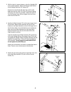
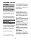
8. Attach a Wheel (66) to the inner side of each Extension
Leg (63) with a Wheel Bolt (64) and a Wheel Nut (13) as
shown.
Do not overtighten the Wheel Bolt. The Wheel
should be able to spin freely.
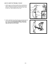
Lift the treadmill frame (see HOW TO FOLD THE
TREADMILL FOR STORAGE on page 11), but do not
latch it. Make sure that the frame is centered between the
Handrails (not shown).
Firmly tighten the bolts used in
assembly step 4. Then, lower the frame to the floor.
63
64
66
13
2
72
48
Ties
8
Opening
7
5-wire
Connector
42
3-wire
Connector
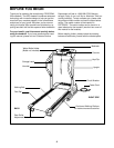
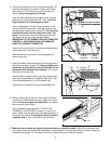
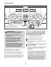
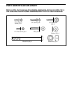
6. Place the Console Base (47) on the Right Handrail (72)
and the Left Handrail (not shown). Attach the Console
Base with four 3/4” Screws (2) (only two Screws are
shown).
Do not overtighten the Screws.
Insert the Wire Harness (42) through the two indicated
plastic ties on the Console Base (47). Next,
touch the
Right Handrail (72) to discharge any static.
Refer to drawing 6b. Find the 3-wire connector on the
end of the Wire Harness (42). Insert the connector into
the red socket beneath the Console (43).
The connector
should slide easily into the socket and “snap” into
place.
If the connector does not slide easily and snap
into place, turn the connector and then insert it.
IMPORTANT: IF THE CONNECTOR IS NOT INSERTED
PROPERLY, THE CONSOLE MAY BE DAMAGED
WHEN THE POWER IS TURNED ON.
Insert the 5-wire connector into the black socket beneath
the Console (43) in the same way.
Make sure that the connectors and wires appear as
shown at the right.
43