


21
Inspect and tighten all parts of the elliptical exerciser
regularly. Replace any worn parts immediately.
To clean the elliptical exerciser, use a damp cloth and
a small amount of mild soap. Important: To avoid
damage to the console, keep liquids away from
the console and keep the console out of direct
sunlight.
BATTERY REPLACEMENT
If the console displays become dim, the batteries
should be replaced; most console problems are the
result of low batteries. See assembly step 5 on page 8
for replacement instructions.
HANDGRIP PULSE SENSOR TROUBLESHOOTING
If the handgrip pulse sensor does not function proper-
ly, see step 5 on page 16.
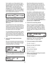
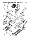
HOW TO ADJUST THE REED SWITCH
If the console does not display correct feedback, the
reed switch should be adjusted. First, remove all of the
screws from both side shields; there are three sizes
of screws in the side shields—note which size of
screw you remove from each hole. Then, gently pry
the side shields away from the frame.
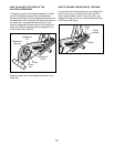
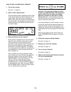
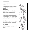
Next, locate the
Reed Switch (58).
Turn the Left
Pedal Disc (26)
until the Magnet
(41) is aligned
with the Reed
Switch. Loosen,
but do not
remove, the indi-
cated M4 x
16mm Screw
(84). Slide the
Reed Switch slightly closer to or away from the
Magnet, and then retighten the Screw. Rock the Left
Pedal Disc forward and backward just enough that the
Magnet passes the Reed Switch repeatedly. Repeat
until the console displays correct feedback. When the
Reed Switch is correctly adjusted, reattach the side
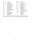
shields. Note: If you have questions as to which screw
should be in which hole, see EXPLODED DRAWING
B on page 27 and the PART LIST on page 24.
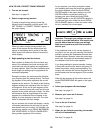
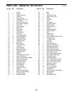
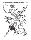
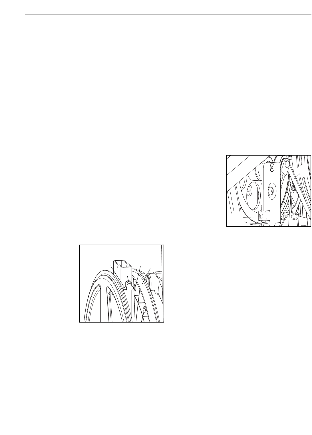
HOW TO ADJUST THE BELT
If you can feel the pedals slip while you are pedaling,
even when the resistance of the pedals is at the high-
est setting, the Belt (46) may need to be adjusted.
First, remove all the screws from both side shields;
there are three sizes of screws in the side
shields—note which size of screw you remove
from each hole. Then, gently pry the side shields
away from the frame.
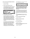
Next, turn the
Belt Adjustment
Screw (72) until
the Belt (46) is
tight. Then, reat-
tach the side
shields. Note: If
you have ques-
tions as to which
screw should be
in which hole,
see EXPLODED
DRAWING B on page 27 and the PART LIST on page
24.
MAINTENANCE AND TROUBLESHOOTING
84
41
26
58
72
46