If]
Fig
If’
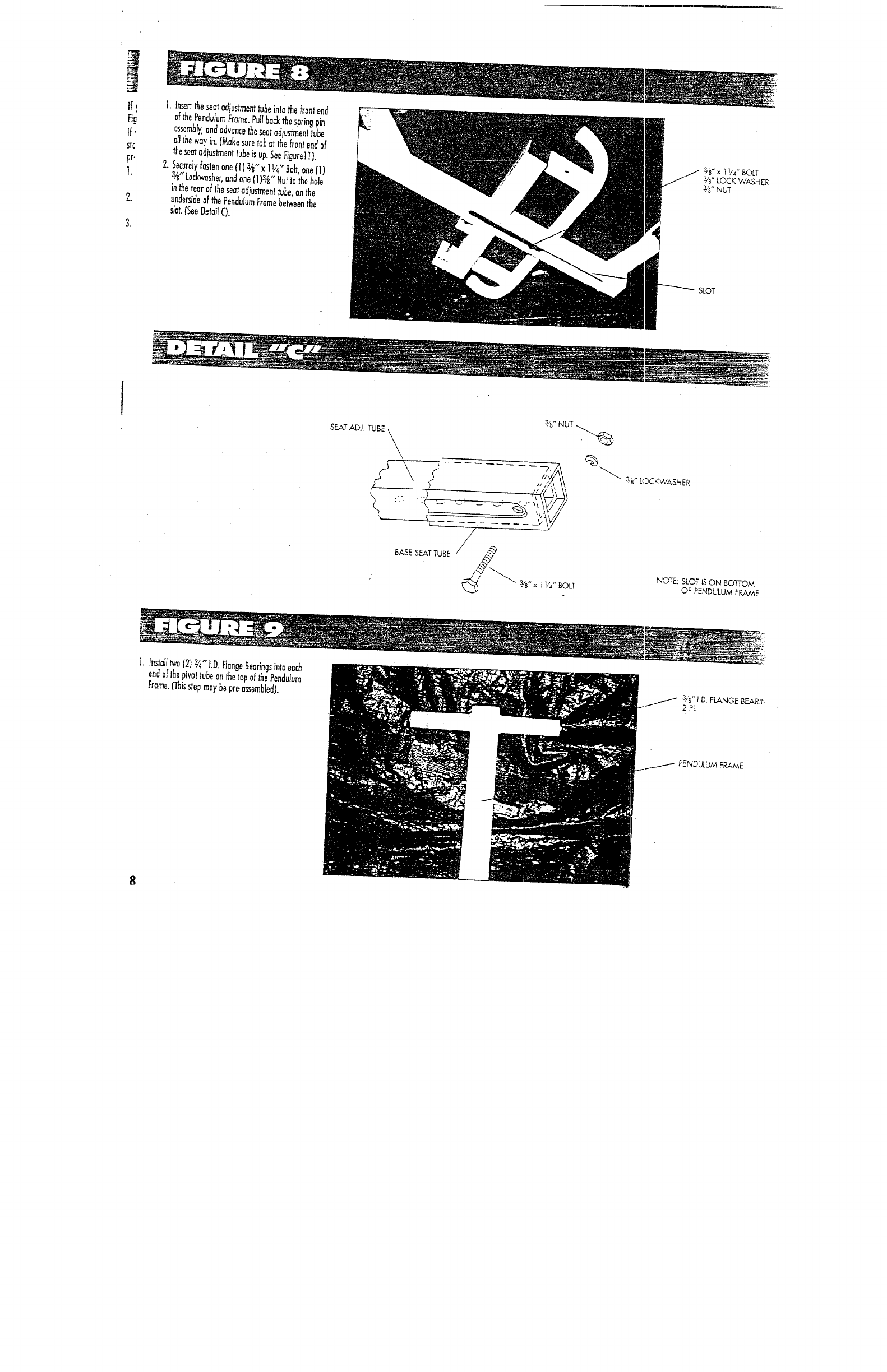
1.
nser~ the seat adjustment tube Into the front end
of the Pendulum flame. Pull back the spring pin
a~mb/y, and advance the seat adjustment tube
al1 the way in. (Make sure tab ai the front end of
the seat adiustment tube is up. See figure] I).
2..Securely fasten one fl) 3~,’ x 1 ]/4" Bob one (1)
~’~" ~ 1,4 BOLT
3/e" Lockwasher, and one (1 }3,~,, Nut to ~he hole s,,~- LOCK WASHE~
in ~e rear of the seat adju~ment tube, on the
W ~
unde~ide of the Pendulum Frame be~een the
sbt. ~See Detai~ C}.
SLOT
3z~
~
LOCKWASHER
NOTE:
SLOT IS ON BOTTOM
OF PENDULUM FRAME
] Install t~a (2) ~ D Flange Bearings Into each
""
end of the pivot tube on the lop of the Pendulum
Frame. ~is step may be pre-assembbd).
3,,~,, I.D. F~NGE B~R~,
2 PL
PENDULUM FRAME


