NOTE:
PROSYSTEIVI PEC DEC OPTION ASSEMBLY INSTRUCTIONS.,
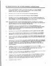
SECURELY as:~emble one (I) 4-I ’20.D. X 1 IN. BUSttlNG PUI.LEY to the LO\
~,
ER PULLEY
SUI’PORT. using one (I) 3/8 X I-3/4 IN. BOLT, one (I) 3/8 I,OCK WASHER, a,~d o,~e (1) 3/8 IN.
LOOSELY assemble one (1) 4-1/20.D. X I IN. BUSIIING PULLEY and one (1) CABLE RETAINING
CLIP to the PULLEY LOOP BRACKET, using one (1) 3/8 X 1-3/4 IN. BOLT, one (1) 3/8 IN.
WASHER, and one (1) 3/8 IN. NUT. (SEE DETAIL
BEFORE PROCEEDING WITH CABLE INSTALLATION, UNRAVEL CABLE, AND REMOVE
AS MUCH SPIRALING AS POSSIBLE.
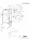
To install LOOP CABLE (PB2598-1), start by SECURELY assembling both ends of the LOOP CABLE
to the CAMS of the LEFT and RIGHT PEC-DEC ARMS, using two (2) 5/16 X 1 IN. BOLTS, four (4)
5/16 IN. WASHERS, two (2) 5/16 IN. LOCK WASHERS, and two (2) 5/16 IN. NUTS. (NOTE:
SURE THE CABLE ENDS REST FLAT AGAINST THE INSIDE OF THE CAMS) (SEE DETAI[L
C)
Drape both sides of the CABLE over the PULLEYS on the PULLEY MOUNT SUPPOR’r. Position
CABLE RETAINING CLIPS on the PULLEY MOUNT SUPPORT in a vertical position over the
PULLEY and CABLE, after the LOOP CABLE has been routed. Tighten the PULLEY CONNECTION
completely.
Place the PULLEY on the PULLEY LOOP BRACKET over the LOOP of the CABLE created from the
above step. Position the CABLE RETAINING CLIP in a vertical position under the CABLE and
PULLEY. Tighten PULLEY CONNECTION completely. (NOTE: MAKE SURE THAT THE
CABLE IS IN THE GROOVE OF THE PULLEY BEFORE TIGHTENING)
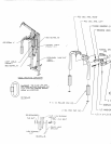
See CABLE ROUTING DIAGRAM for help in completing STEP 16.
To install SECONDARY SWAP-OUT CABLE (PB2599-1), start by inserting the end of the CABLE,
WITHOUT the WHITE BALL under the FRONT PULLEY in the LOW ROW PULLEY IHOUSING
on the MAIN UPRIGHT. (REMOVE PULLEY FOR EASE OF INSTALLATION)
Push the CABLE under the FRONT PULLEY and througl: the HOLE of the MAIN UPRIGHT to the
PULLEY on the UPRIGHT BRACE of the MAIN UPR!CHT. Pull CABLE until the WHITE BALL
stops against the FRONT PULLEY and the LOW ROW PULLEY HOUSING.
Pull the CABLE around the BRACE PULLEY and up to the SECOND PULLEY on the PULLEY
BLOCK SYSTEM. (NOTE: THE CABLE MUST BE ROUTED AROUND THE SECOND PULLEY
FROM THE REAR TO THE FRONT)
Pull CABLE around the SECOND PULLEY of the PULLEY BLOCK SYSTEM and down to the
PULLEY on the LOWER PULLEY SUPPORT. Pull CABLE around underneath the PULLEY, and
attach it to the HOLE of the PULLEY LOOP BRACKET, using 1/4 IN. QUICK LINK. (SEE DETAIL
A)
See CABLE ROUTING DIAGRAM for help in completing STEP 17.
If assembling the PEC DEC OPTION and the MAIN UNIT at the same time, return to the I~/IAIN UNIT
ASSEMBLY IINSTRUCTIONS, and continue on with STEP 25.


