


894
NOTE:
10.
II.
12."
13.
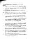
PROSYSTEM PEC DEC OPTION ASSEMBLY INSTRUCTIONS
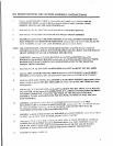
Remove the SECONDARY CABLE by disassembling the CABLE from its ,M.,~IX UPRIGIII’I"
CONNECTION POINT, and pull CABLE out from the LOW PULLEY STATION. (NOTIE:
REMOVE LG,W PULLEY FOR EASE OF REMOVAL)
Insert four (4) 2 IN. SQ. END CAPS into all open ends of the BEARING ltOt.!SING.
Insert one (I) ";’. IN. SQ. END CAP into the end of the PULLEY MOUNT SUPPORT,
SECURELY ~ssemble both the BEARING HOUSING and the PULLEY MOUNT SUPPOR’[ to the
MAIN UPRIGHT of the BODYSMITH PROSYSTEM, using two (2) I~ X 3-I,r2 IN. BOLI’S, four
1/2 IN. WASHERS, two (2) t/2 IN. LOCK WASHERS, and two (2) 1,2 IN. NUIS.
THE CONNECTOR PLATES ON THE BEARING HOUSING AND TIlE PI.:i, LEY MOUNT
SUPPORT HA.VE OVAL HOLES. MOVE THE BEARING HOUSING DO~,VN AND TIlE PULLEY
MOUNT SUPPORT UP AS FAR AS POSSIBLE. SEE-DRAWING
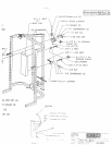
CAREFULLY insert tour (4) FLANGE BEARINGS into the TOP and BOTTOM side~ of the
BUSHINGS of the BEARING HOUSING on both sides. (CAUTION: DO NOT OVER TAP TItESE
BEARINGS INTO PLACE, WHICH CAN CAUSE DEFORMATION TO TIlE BEARINGS,
MAKING THEM UNUSABLE)
Insert four (4) 2 IN. SQ. END CAPS into BOTH ENDS of the LEFT and RIGliT PEC-DEC ARMS.
Insert the LEFT and RIGHT PEC-DEC ARMS through the FLANGE BEARINGS in the BEARING
HOUSING on their respective sides, and secure them in place with two (2) STAR LOCK COLLARS.
Attach two (2) PLASTIC STOPS to the CAM STOP on the BEARING HOUSING, approximately where
shown, in orde.r to give the PEC-DEC ARM CAMS full contact when the PEC-DEC ARMS ~tre in their
resting positio~a.
Slide two (2) 4 X 12 ROLLER PADS onto the LEFT and RIGHT PEC-DEC ARMS. until the ROLLER
PAD is FLUSH with the bottom of the ARMS.(NOTE: IF A LUBRICANT IS REQUIRED, RUBBING
ALCOHOL THOROUGHLY COATING THE INSIDE OF THE ROLLER IS TIlE BF2~-I"
MATERIAL TO USE. ALSO, ROTATING THE PAD ~’HILE PUSHING UP WILL llELP TO
EASE ASSEMBLY)
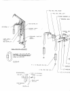
LOOSELY assemble two (2) 4-1/20.D. X I IN. BUSHING PULLEYS and tx~o {2} CAIILI:’.
RETAINING CLIPS to the PULLEY MOUNT SUPPORT. usiqg tx~o (2~
IN. LOCK WASHERS, and two (2) 3/8 IN. NUTS. (NOTE: Tills CONNECTION X~II..i.
TIGHTENED AFTER THE CABLE HAS BEEN ROUTED)
LOOSELY assemble the BACK PAD to the TOP HOLE of the MAIN VPRIGlt I. u,,mg t~,ne ( i } 3;g X
IN. BOLT, one (1) 3/8 IN. LOCK WASHER, and one (!) 3,’8 IN. ~,VASllER
Using one (1)3/8 X 3-I/4 IN. BOLT, and one (I)3i8 IN. LOCK WASIIER. SECt REI.~’ assemble
LOWER PULLEY SUPPORT through the BOTTOM HOLE of the MAIN UI’RIf;liT and into the
BACK PAD. (NOTE: MAKE SURE THAT THE BASE PLATE OFTilE L¢)~ t:R I’ILLEY
SUPPORT IS FLUSH WITH THE SIDES OF THE MAIN UI’RI(;IIT. SEE I)R.~I~(J;I
TIGHTEN the BOLr in STEP ! I.