


893102 PROSYSTEM ASSEMBLY INSTRUCTIONS
11.
12.
13.
14.
15.
16.
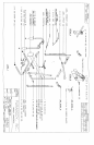
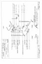
LOOSELY assemble the LEFT and RIGHT BOOM SUPPORT WELDMENTS to the TOP BOOM
WELDMENT as shown.
LOOSELY assemble the UPRIGHT WELDMENTS to the LEFT and RIGHT BOOM ’3UPPORT
WELDMENTS as shown.
SECURELY TIGHTEN ALL LOOSE BOLT CONNECTION MADE TO THIS POINT.
Assemble the 4 X 7 IN. ROLLER PADS with MUSHROOM CAPS to the SWIVEL KNEE SUPPORT
WELDMENT as shown, also assemble one (1) SPRING PIN ASSEMBLY to the SWIVEL KNEE
SUPPORT WELDMENT as shown in (DETAIL D) then SECURELY assemble it to the UPRIGHT
FRAME ~TLD2"~IENT as shown. (NOTE: DO NOT OVER TIGHTEN THIS CONNECTION, THE
SI.VII~L KNEE SUPPORT IVELDMENT SHOULD ROTATE FREELY)
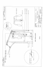
Insert two (2) 2 IN. SQ. END CAPS into the BEARING HOUSING WELDMENT as shown, then
SECURELY assemble it along with the CENTER PULLEY BRACKET WELDMENT to the UPRIGHT
FRAME WELDMENT as shown.
Insert four (4) 2 IN. SQ. END CAPS into the LEFT and RIGHT PEC ARM WELDMENTS as shown,
then assemble them to the BEARING HOUSING WELDMENT as shown. Also attach tw? (2) 1 IN. SQ.
GLIDES to the BEARING HOUSING WELDMENT as shown.
SECURELY assemble the PAD to the UPRIGHT FRAME WELD3/IENT as shown, Also slide the 4 X
12 IN. ROLLER PADS onto the LEFT and RIGHT PEC ARM WELDMENTS as shown. (TIY’: USE
WINDOW CLEANER ON THE INSIDE OF THE ROLLER PAD TO tIELP EASE ASSEMBLY)
PULLEY ASSEMBL Y:
A.
LOOSELY assemble four (4) 3-1/2 X 1 IN. PULLEYS with CABLE RETAININC, CLIPS to the
UPRIGHT FRAME WELDMENT, and the CENTER PULLEY BRACKET WELDMENT as
shown in (DETAIL C)
B. LOOSELY assemble one (1) 3-1/2 X 1 IN. PULLEY with FLANGE SPACERS at the bottom
the UPRIGHT FRAME WELDMENT as shown.
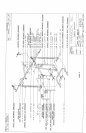
HIGH PULLEY CABLE ROUTING ASSE:’vlBL Y (SEE CABLE ROUTING DIAGRAiPI):
A. Attach the pre-assembled CABLE from the TOP BOOM WELDMENT to the CAtLrCJA GE
WELDMENT as shown.
B, *, Create a loop in the CABLE below the first and second PULLEY of the TOPBOOM
WELDMENT, and place one (1) 3-1/2 X 1 IN. PULLEY into the loop. LOOSELY assemble the
1-374 X 5-1/4 IN. PLATES to the PULLEY as shown.
C.
Assembleone(1)3-1/2XlIN, PULLEYtothebottomholesofthel-3/4XS-IA4IN. PLATES
as showl~.
PEC ARM CABLE ROUTING ASSEMBL Y (SEE CABLE ROUTING DIAGRAkI):.
A. Attach the ends of CABLE (6492201) tothe LEFT and RIGHT PEC ARM WELDMENTS as
shown.
B. Drape the CABLE over the two (2) PULLEYS on the CENTER PULLEYBRACIfET
WELD3IENTwhich will create a loop in the CABLE. (NOTE: AFTER CABLE IS ROUTED
OVER PULLEYS, POSITION CABLE RETAINING CLIPS OVER THE PULLEYS AS
SHOWN AND TIGHTEN)
C. Place one (1) 3-i/2 X 1 IN. PULLEY into the loop of the CABLE, and SECURELY assemble
the PULLEY BRACKET WELDMENT to the PULLEY as shown.
5
12/06/95