1/2X3"~
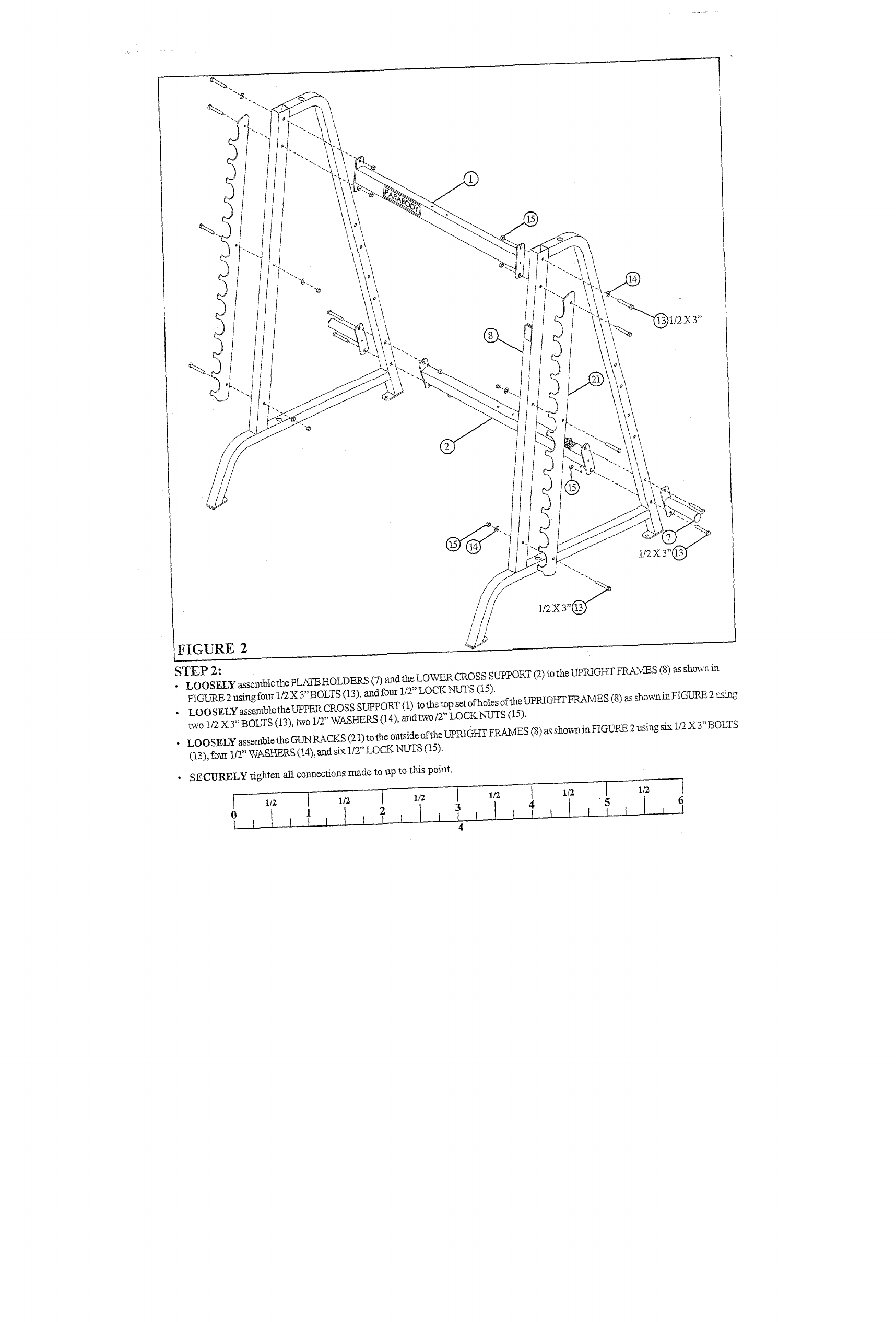
FIGURE 2
STEP 2:
¯
LOOSELY assemblethe PLATEHOLDEP--S (7) andtheLOWERCROSS SUPPORT (2) totheUPRIGIff-f FRAMES (8) as
FIGURE 2 using four 1/2 X 3" BOLTS (13), and four 1/2" LOCKNUTS (15),
¯
LOOSELYassembletheUPPERCROSSSUPPORT(1) tothetopsetofholesoftheupRIGHTFRAMES(8)assh°wninFIGURE2nsing
two 1/2 X3" BOLTS (13), two 1/2" WASHERS (14), andtwo/2" LOCKNUTS (15).
¯ LOOSELY assemble the GUN RACKS (21) to the outside of the UPRIGHT FRAMES (8) as sho~inFIGURE 2 using six 1/2 X 3" BOLTS
(13), fo~ 1/2" WASHERS (14), arid six 1/2" LOCKNUTS (15).
SECURELY tighten all connections made to up to this point.
~ 1/2 I 1/2 i 1/~


