6
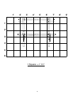
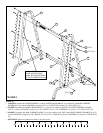
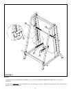
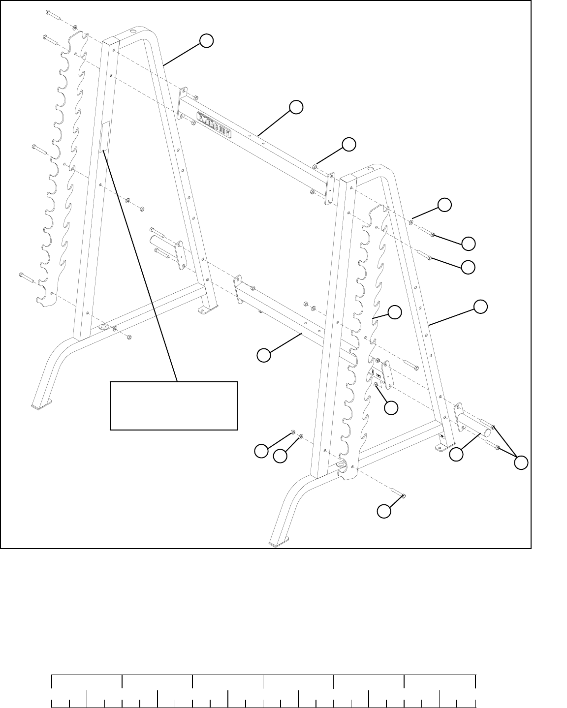
FIGURE 1
STEP 1:
0
1
2
345
6
1/2 1/2 1/2 1/2 1/2 1/2
• LOOSELY assemble the WEIGHT HORNS (7) and the LOWER CROSS BRACE (2) to the LEFT and RIGHT UPRIGHT
FRAMES(8 & 12) as shown in FIGURE 1 using four 1/2 X 3-1/4” BOLTS (18), and four 1/2” LOCK NUTS (15).
• LOOSELY assemble the UPPER CROSS BRACE (1) to the top set of holes of the LEFT and RIGHT UPRIGHT FRAMES
(8 & 12) as shown in FIGURE 1 using two 1/2 X 3” BOLTS (13), two 1/2” WASHERS (14), and two 1 /2” LOCK NUTS (15).
13 1/2 X 3”
1/2 X 3-1/4” 18
7
15
12
2
8
• SECURELY tighten all connections made to up to this point.
15
1/2 X 3” 13
14
15
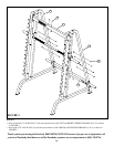
• LOOSELY assemble the BAR SUPPORT RACKS (10) to the outside of the LEFT and RIGHT UPRIGHT FRAMES (8 & 12)
as shown in FIGURE 1 using four 1/2 X 3” BOLTS (13), two 1/2 X 3-1/4” BOLTS (18), four 1/2” WASHERS (14), and six 1/2” LOCK NUTS
(15).
10
1
*NOTE*
MAKE SURE WARNING
LABEL IS FACING INWARD
ON EACH UPRIGHT FRAME
14
18 1/2 X 3-1/4”


