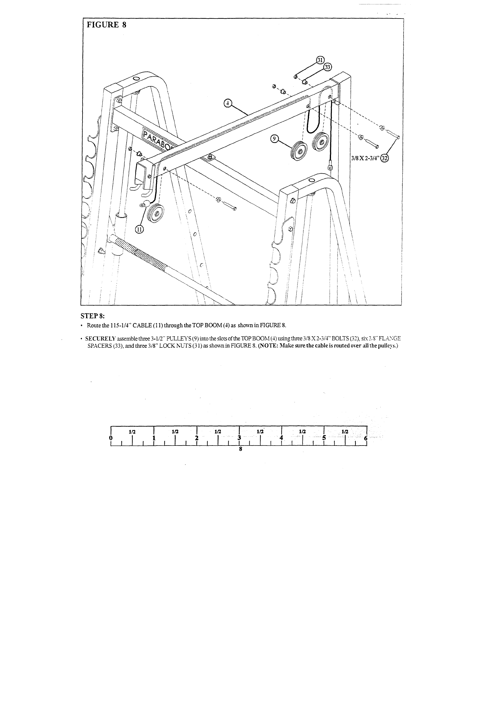
FIGURE 8
3/8 x
STEP 8:
¯ Routethe 115-1/4" CABLE (l l) through the TOP BOOM (4) as sho~vn in FIGURE
¯ SECL’RELY assemble three 3-1/2"" PI]LI EYS (9) into the slots of the TOP BOOM (4) using three 3/8 X 2-3/4" BOLTS (32), six
SPACERS (33), and three 3/8" LOCK N~’TS (31) as sho~.n in FIGLrRE 8. (NOTE: Make sure the cable is routed over "all the pulleys.)


