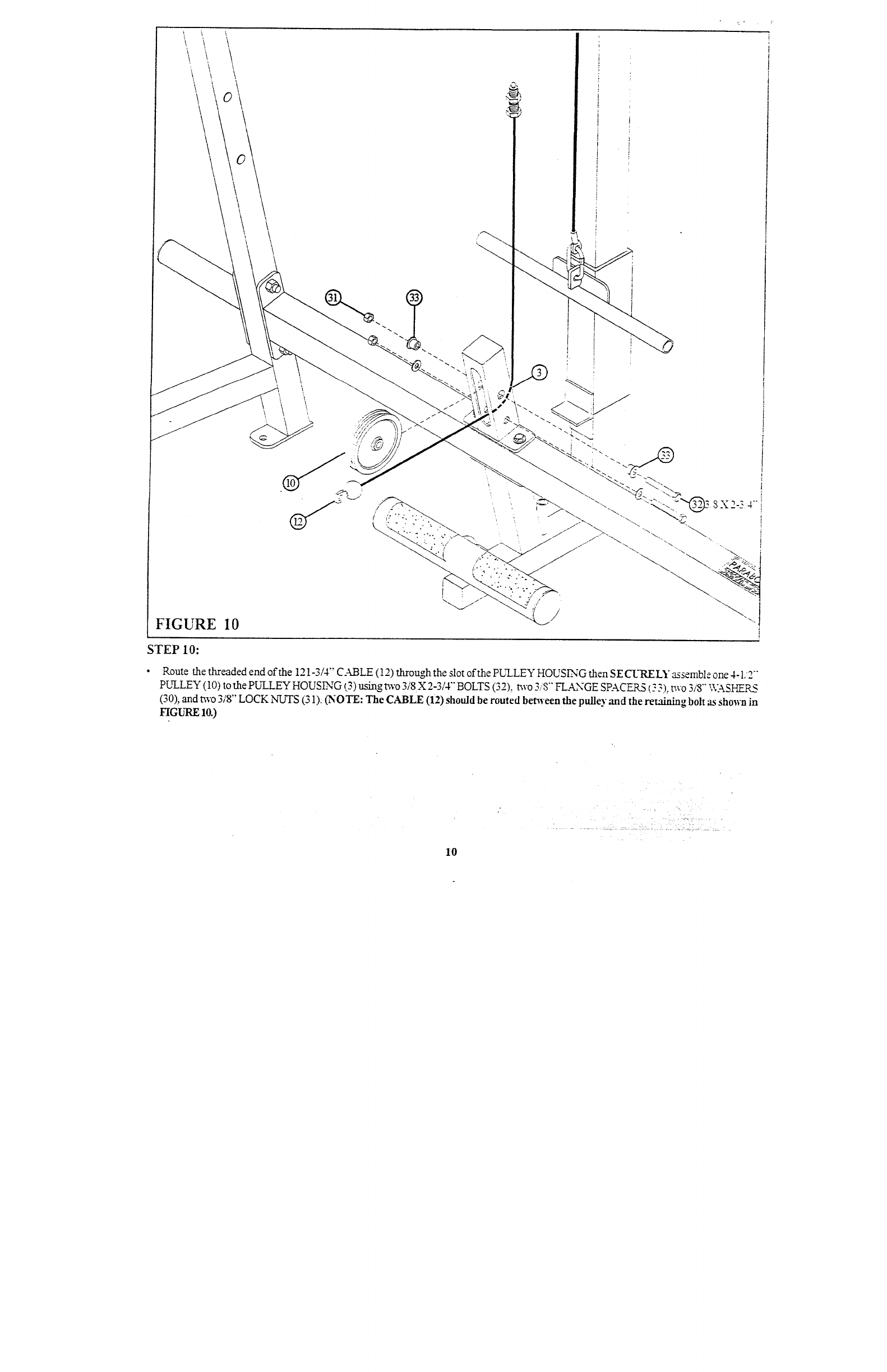
FIGURE 10
STEP 10:
Route the threaded end of the 121-3/4" CABLE (12) through the slot oft.he PULLEY HOUSING then SECURELY assemble one 4-1/2
pLrLLEY (10) to the PU~.I.EY HOUSLNG (3) using t~vo 3/8X 2-3/4"" BOLTS (32), two 3/8"" FLANGE SPACERS (.: 3), two 3/8"" \\:-kSHERS
(30), and two 3/8" LOCK NUTS (31). (NOTE: CABLE (12)should be routed benveen the pulley and the retaining bolt as shown
FIGURE 10.)
10


