


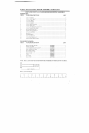
874104 MULTI-ANGLE BENCH ASSEMBLY INSTRUCTIONS
9.
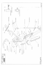
SECURELY Assemble one ( I ) SPRING PIN ASSEMBLY to the SWIVEL, as shown in (DETAIL
10. Insert two (2) 3/4 IN. FLANGE BEARINGS into the BUSHING on the BENCH FRAME as shown
drawing.
h3sert the SHAFT of the SWIVEL through the 3/4 IN. FLANGE BEARINGS on ti~e BENCH FRAME as
shown on drawing, and SECURE in place with one (1) STAR LOCK COLLAR.
12. Insert two (2) 3/4 IN. FLANGE BEARINGS into the BUSHING on the PAD SUPPORT as shown
dra\\.’il~g.
14. [nser~ two (2) I-3/4 IN. SQ. END CAPS into both ends of the ADJUSTMENT SLIDE as shown
drawin,~.
15.
16.
Slide one (1) 3/4"IN. WASIqER over the SHAFT of the ADJUSTMENT SLIDE. Insert the SHAFT
Ihe AD,IUSTMENT SLIDE lhrougl
l
the 3/4 IN. FLANGE BEARINGS on the PAD SUPPORT as shown
on drawing, and SECURE in place with one (1) STAR LOCK COLLAR.
Pull back the SPRING PIN on the SWIVEL, and insert the ADJUSTMENT SLIDE, down t~ the first
adjt|smlent hole. Release the SPRING PIN into the hole.
17. SECURELY attach the BACK PAD to the PAD SUPPORT using foul" (4) 3/8 X 1-1/4 IN.BOLTS, tbur
(4) 3:8 IN. LOCK WASIIERS. and four (4)3/8 IN. WASHERS.
.’-;F.CURELY attach the SEAT PAD to the HINGE TABS using two (2) 3/8 X 1-I/4 IN.BOLTS. two (2)
LOCK WASHERS. and lwo (2) 3/8 IN. WASHERS.
19. [o adjust the SEAT PAD lbr the LEG EXTENSION position, pull out on the U-PIN. Rotate the U-PIN
back pass the FIRST PIN STOP. Release the U-PIN, and allow it to rest up against the FIRST PIN
STOP.
20. ’Fo ad.iust the SEAT PAD ibr rl~e DECLINE or INCLINE position, rotate the U-PIN back to the
SKCONID PIN STOP.
21. The exlra 2 IN. SQ. END CAP is for the top of the UPRIGHT TUBE on the BENCH FRAME. If
attachmenls will be used. this CAP will not be needed.
Ilasert one ( I ) THUMBSCREW into the UPRIGHT TUBE of the BENCH FRAME as shown on drawing.
This will be used for secu|ing attaclu’nents in place.