


I0.
11.
12.
13.
14.
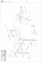
Insert one (1) 3 X 2 IN. END CAP into the top of the UPRIGHT FRAME, and two (2) 2 EN. SQ.
CAPS into the BASE of the UPRIGHT FRAME as shown on drawing. Repeat this step for the second
UPRIGHT FRAME.
SECURELY assemble both UPRIGHT FRAMES to the CROSS BRACE as shown on drawing using
four (4) 1/2 X 3 IN. BOLTS, four (43 1/2 IN. WASHERS, and four (4) 1/2 IN. LOCK NUTS;.
(IMPORTANT: THE ANGLE BRACKETS ON THE CROSS BRACE ARE OFFSET, PLEASE
MAKE SURE THAT THE LONGEST END OF THE BRACKET IS FACING UP BEFORE
ASSEMBLY)
SECURELY assemble the BENCH FRAME to the CROSS BRACE as shown on drawing using two (2)
1/2 X 3 IN. BOLTS, two (2) 1/2 IN. WASHERS, and two (2) I/2 IN. LOCK NUTs. Attach one 2"
cover cap to the BENCH FRAME as shown.
Insert two (2) 1/2 IN. FLANGE BEARINGS into each end of the BUSHING of the BENCtt FRAME
shown on drawing.
SECURELY assemble the BENCH SLIDE to the BUSHING of the BENCH FRAME as ~hown on
drawing, using one (1) 1/2 X 3-1/2 IN. BOLT one (1) 1/2 IN. LOW HT LOCK
Attach eight (8) 1-1/2 X 3/4" GLIDES to the WOLFF SLEEVE (FOUR ON EACH END) as shown
(DETAIL A) using the following steps:
Thoroughly clean all surfaces where the GLIDES are to be attac1~ed.
Remove the GLIDES from the paper backing and firmly apply them to all shown surfaces.
Insert one (1) U-PIN through the BUSHING of the WOLFF SLEEVE as.shown on drawing, and attach
one (I) PAL NUT to the end of the U-PIN.
SECURELY Assemble one (1) SPRING PIN ASSEMBLY to the SPRING PIN BARREL, of the
WOLFF SLEEVE as shown in (DETAIL B). (!!! IMPORTANT !!! TIG~ITEN THE NUT OF
SPRING PIN ASSEMBLY SECURELY)
Pull back the SPRING PIN on the WOLFF SLEEVE and slide it over the end of the BENCH SLIDE as
shown on drawing. Engage the SPRING PIN into one of the adjustment hole
s.
Secure the WOLFF
SLEEVE in place with one (1) 3-PRONG KNOB.
LOOSELY assemble one (1) 3 PRONG KNOB to the UPRIGHT TUBE of the BENCH FRAME
shown on drawing. (THIS WILL BE USED TO SECURE ATTACHMENTS IN PLACE)
Attach one (1) 1-1/4 IN. S Q. RUBBER BUMPER to the SLIDE SUPPORT as shown on drawing.
SECURELY assemble the SLIDE SUPPORT to the end of the BENCH SLIDE as shown on drawing
using one (I) 3/8 X 2-3/4 IN. BOLT, two (2) 3/8 IN WASHERS, and one (1) 3/8 IN. LOCK
Attach two (2) 1 X 1 GLIDES to the top of the BENCH FRAME where the SLIDE SUPPORT makes
contact. See drawing.
Assemble the SEAT PAD to the WOLFF SLEEVE, start by sliding two (2) HINGE TABS over the PIN
of the WOLFF SLEEVE (ONE ON EACH SIDE) as shown on drawing, and SECURELY assemble
each HINGE TAB to the SEAT PAD using two (2) 3/8 X 1-1/4 IN. BOLTS and two (2) 3/8
WASHERS. (MAKE SURE BOTH HINGE TABS ARE ALL THE WAY ON THE PIN)
Part # 6611901
3 Revision: 04/30/96